
SRAM employing virtual rail scheme stable against various process-voltage-temperature variations

a virtual rail and voltage-temperature variation technology, applied in the direction of information storage, static storage, digital storage, etc., can solve the problems of data reading operation instability, data reading from an sram cell becomes more difficult, etc., and achieve the effect of stable low-leakage current characteristics

Active Publication Date: 2006-09-19
SAMSUNG ELECTRONICS CO LTD
View PDF10 Cites 114 Cited by
  • Summary
  • Abstract
  • Description
  • Claims
  • Application Information

AI Technical Summary

Benefits of technology

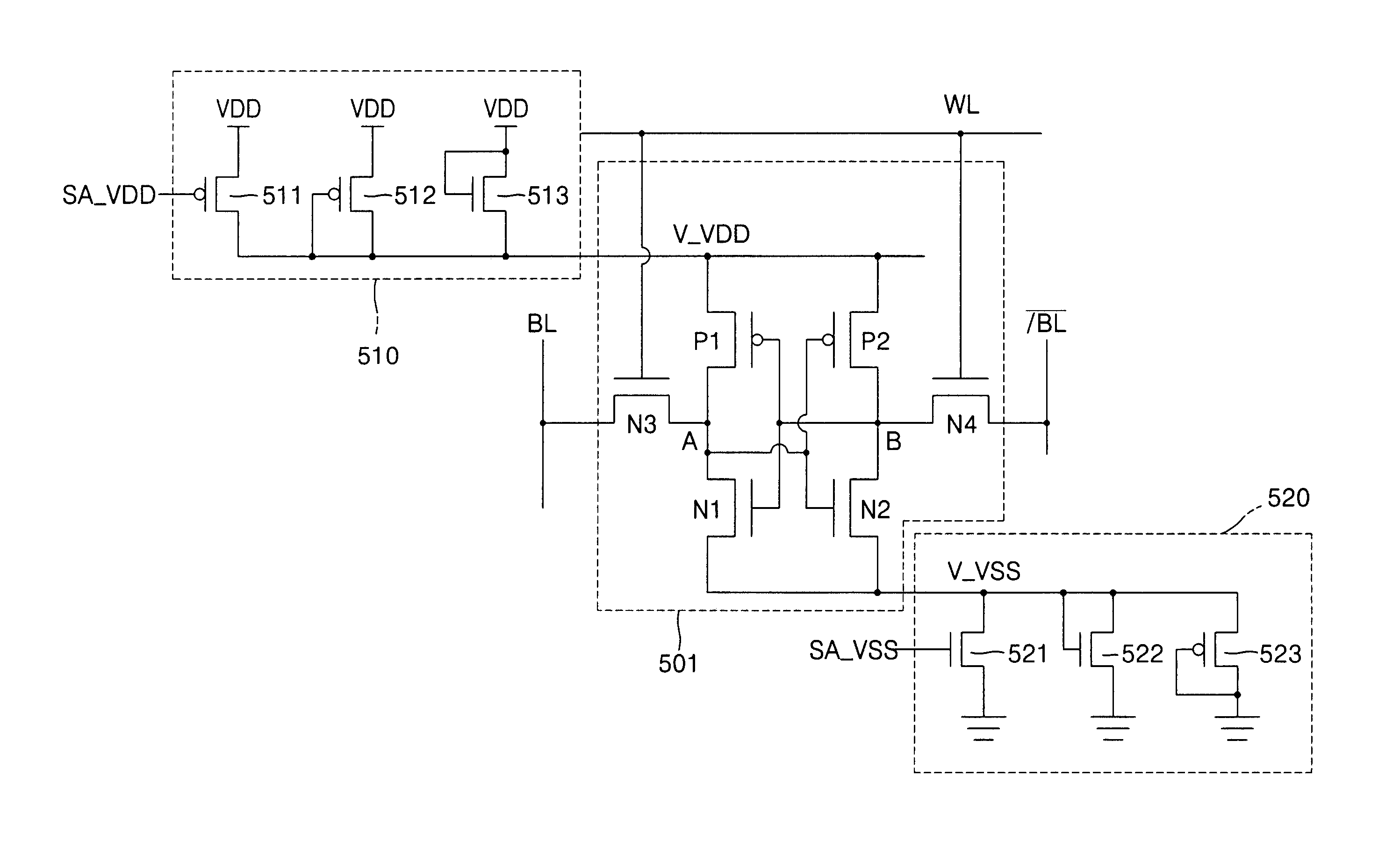
The present invention provides a low leakage current SRAM that provides a stable virtual rail with various process-voltage-temperature (PVT) variations. This is achieved by using a first bias device to supply a virtual power supply voltage to the SRAM cells in a low leakage current mode and a second bias device to supply the virtual power supply voltage in an active mode. The first bias device includes a first PMOS transistor, a second PMOS transistor, and a third NMOS transistor. The second bias device includes a first NMOS transistor, a second NMOS transistor, and a third PMOS transistor. The virtual power supply voltage has a voltage level obtained by lowering the power supply voltage by a threshold voltage of the second PMOS transistor, and the virtual ground voltage has a voltage level obtained by raising the ground voltage by a threshold voltage of the second NMOS transistor. This ensures stable low-leakage current characteristics for the SRAM regardless of process-voltage-temperature variations.

Problems solved by technology

With increased leakage current, the reading of data from an SRAM cell becomes more difficult, and an approach for of reducing the leakage current from each SRAM cell is required.
At portion ΔB, the leakage current is small but the read current of the SRAM cell decreases, so that the SRAM cell performs unstable reading operations.

Method used


Image

  • SRAM employing virtual rail scheme stable against various process-voltage-temperature variations
  • SRAM employing virtual rail scheme stable against various process-voltage-temperature variations
  • SRAM employing virtual rail scheme stable against various process-voltage-temperature variations

Examples


Embodiment Construction

[0033]The attached drawings for illustrating preferred embodiments of the present invention are referred to in order to gain a sufficient understanding of the present invention, the merits thereof, and the objectives accomplished by the implementation of the present invention.

[0034]Hereinafter, the present invention will be described in detail by explaining preferred embodiments of the invention with reference to the attached drawings. Like reference numerals in the drawings denote like elements.

[0035]FIG. 5 illustrates a SRAM having a virtual rail scheme according to an embodiment of the present invention. Referring to FIG. 5, an SRAM cell 501 is configured substantially the same as the SRAM cell 101 of FIG. 1 except that sources of transistors P1 and P2 are not connected to a power supply voltage VDD but rather are connected to a virtual power supply voltage V13 VDD transmitted via a first bias device 510 and that sources of transistors N1 and N2 are not connected to a ground volt...


PUM


Abstract

An SRAM employs a virtual rail configuration that is stable against process-voltage-temperature (PVT) variation. The SRAM provides a virtual power supply voltage to an SRAM cell that is obtained by lowering a power supply voltage by a threshold voltage of a transistor and a virtual ground voltage obtained by raising a ground voltage by a threshold voltage of a transistor. Due to the use of PMOS and NMOS transistors of diode types connected between the power supply voltage and the virtual power supply voltage and the use of NMOS and PMOS transistors of diode types connected between the ground voltage and the virtual ground voltage, a virtual power supply voltage level and a virtual ground voltage level that are stable even against various PVT variations are provided, so that low-leakage current characteristics are stable.

Description

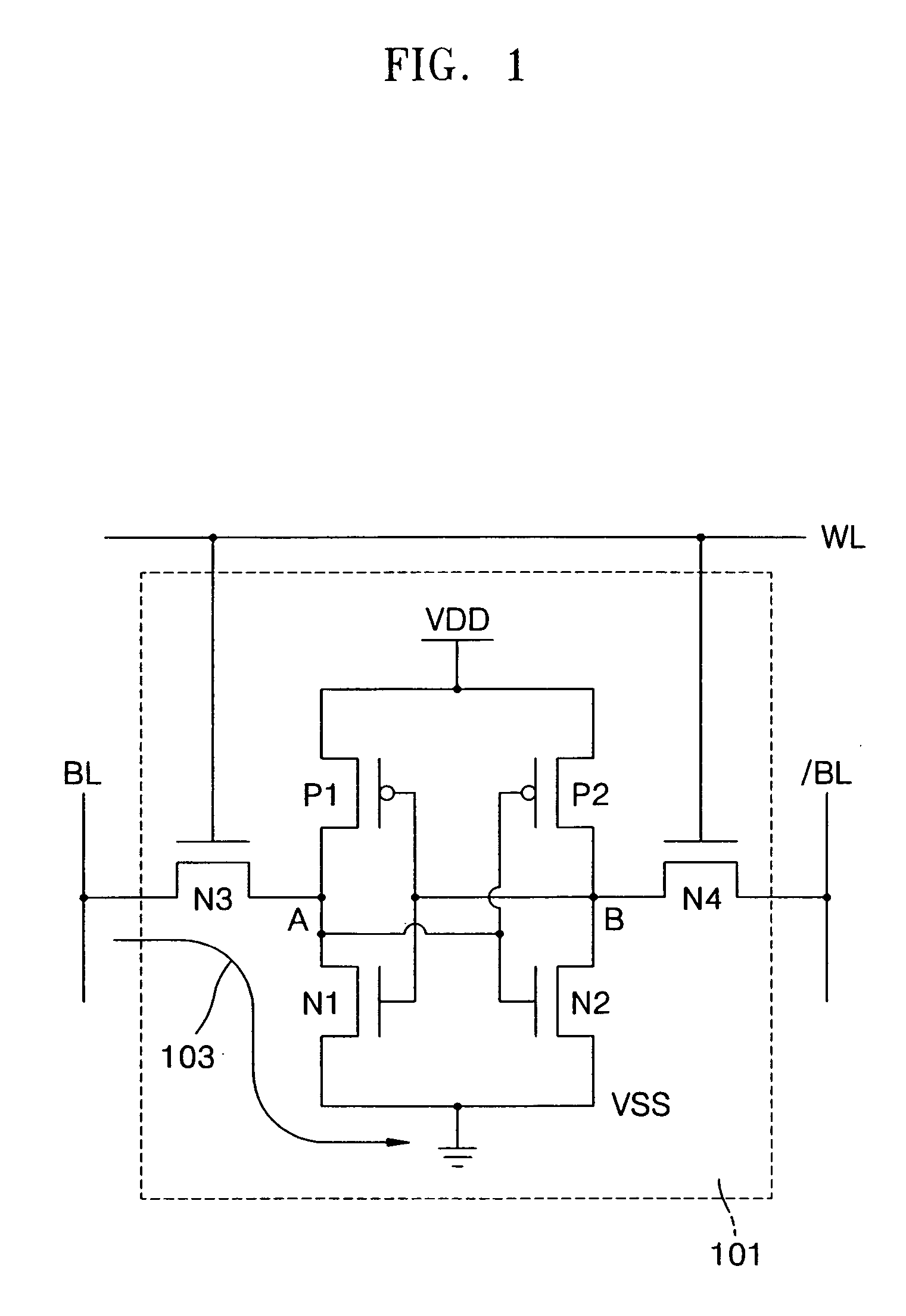
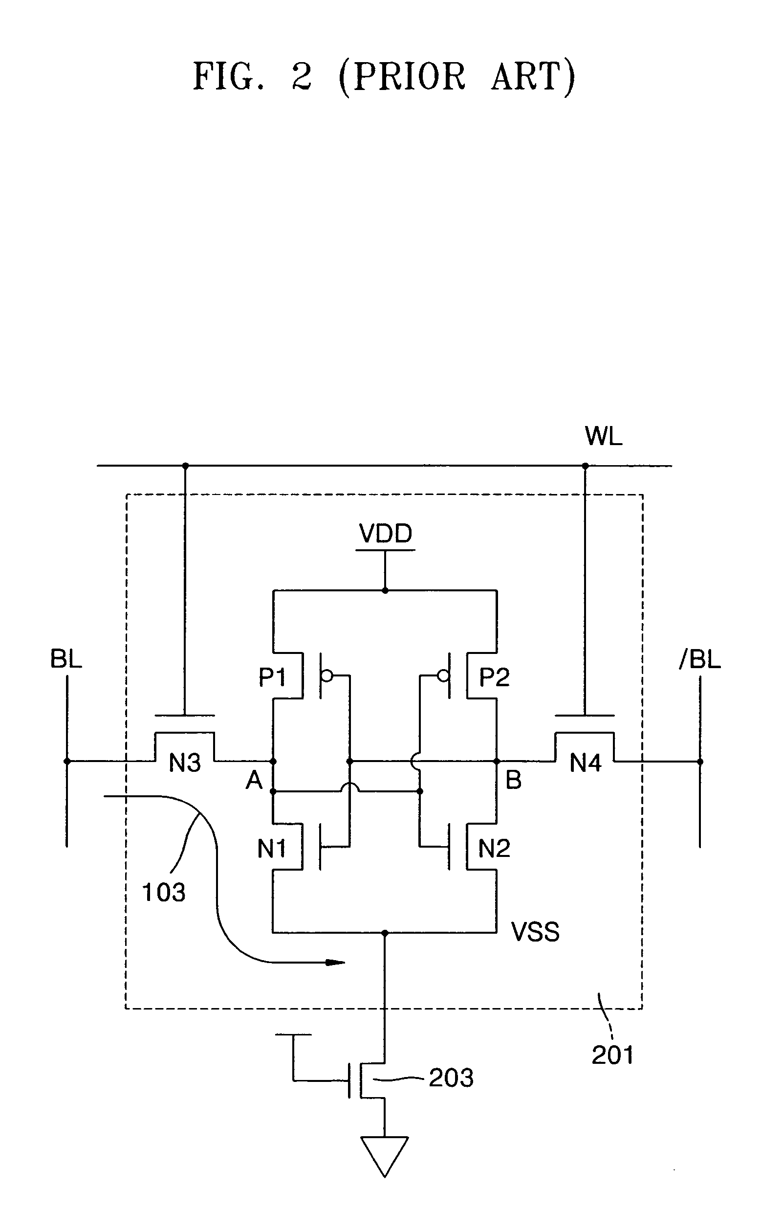
BACKGROUND OF THE INVENTION[0001]This application claims the benefit of Korean Patent Application No. 2004-51525, filed on Jul. 2, 2004, in the Korean Intellectual Property Office, the disclosure of which is incorporated herein in its entirety by reference.[0002]1. Field of the Invention[0003]The present invention relates to a semiconductor memory device, and more particularly, to a synchronous random access memory (SRAM) device employing a virtual rail scheme that is stable against various process-voltage-temperature (PVT) variations.[0004]2. Description of the Related Art[0005]FIG. 1 is a circuit diagram of an SRAM cell 101, which is generally used in an SRAM memory array and comprised of 6 transistors. The SRAM cell 101 is well known as a 6T SRAM cell. In the SRAM cell 101, NMOS transistors N1 and N2 are connected between a ground voltage VSS and a node A and between the ground voltage VSS and a node B, respectively, and the nodes A and B are connected to a power supply voltage V...

Claims


Application Information

Patent Timeline
Patent Type & Authority Patents(United States)
IPC IPC(8): G11C5/14G11C11/00
CPCG11C11/417G11C5/14G11C11/413
Inventor SONG, TAE-JOONGCHOI, JAE-SEUNG
Owner SAMSUNG ELECTRONICS CO LTD
Learn More