Master medium for magnetic transfer and magnetic disk and magnetic disk drive
a magnetic transfer and master medium technology, applied in the field of magnetic transfer apparatuses, can solve problems such as disturbing the servo control of the head, and achieve the effect of sufficient intensity or strength
- Summary
- Abstract
- Description
- Claims
- Application Information
AI Technical Summary
Benefits of technology
Problems solved by technology
Method used
Image
Examples
first embodiment
[0056]FIG. 1 schematically illustrates the outline of a hard disk drive (HDD) 11 as an example of a magnetic recording drive or storage device according to the present invention. The HDD 11 includes a box-shaped enclosure 12. The enclosure 12 includes an enclosure body 13 defining an inner space of a flat parallelepiped, for example. The enclosure body 13 may be made of a metallic material such as aluminum, for example. Molding process may be employed to form the enclosure body 13. A cover 14 is coupled to the enclosure body 13, so that the inner space of the enclosure body 13 is airtightly isolated from the exterior space. The cover 14 may be formed of a single plate material based on pressing process, for example. The plate material may be a layered material having a damping property to vibration.
[0057]The HDD 11 allows elimination of a bore, receiving an insert pin, from the cover 14 of the enclosure 12. The structure of the cover 14 is simplified. The simplified structure leads ...
second embodiment
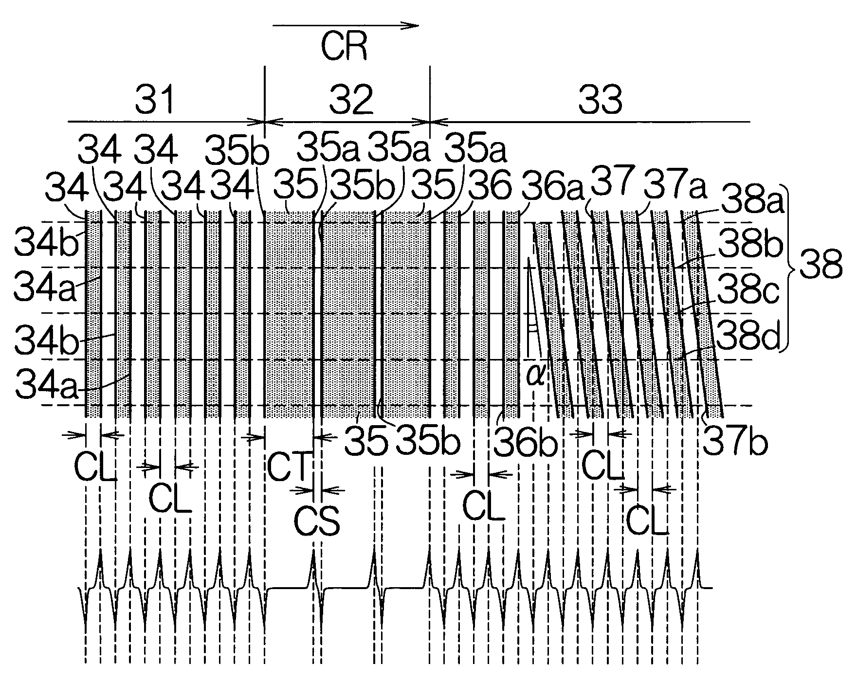
[0102]A HDD according to the present invention includes a magnetic recording disk 17a, in place of the magnetic recording disk 17, within the enclosure 12. As shown in FIG. 11, a preamble region 81, a servo mark region 82 and a servo data region 83 are, in this sequence from the upstream end, formed in the individual servo sector region 28 on the magnetic recording disk 17a, for example. The preamble and servo data regions 81, 83 have structures identical to that of the aforementioned preamble and servo data regions 31, 33. It should be noted that the magnetizations butt against each other at the upstream contours 34b of the individual synchronization magnetized stripes 34 in the preamble region 81. The positive magnetic poles are thus established along the upstream contours 34b of the synchronization magnetized stripes 34. On the other hand, the magnetizations are directed apart in the opposite directions at the downstream contours 34a of the synchronization magnetized stripes 34. ...
fourth embodiment
[0116]A HDD according to the present invention includes a magnetic recording disk 17c, in place of the magnetic recording disk 17, within the enclosure 12. As shown in FIG. 18, a preamble region 111, a servo mark region 112 and a servo data region 113 are, in this sequence from the upstream end, formed in the individual servo sector region 28 on the magnetic recording disk 17c, for example. The preamble and servo mark regions 111, 112 have structures identical to that of the aforementioned preamble and servo mark regions 31, 102.
[0117]The servo data region 113 includes a referential information region 114 dividing magnetizations by radii of the magnetic recording disk 17c. The reference magnetized stripes 36 are established within the referential information region 114 in the same manner as described above. A first positional information region 116 is formed downstream of the referential information region 114. The first positional information region 116 is designed to divide magnet...
PUM
| Property | Measurement | Unit |
|---|---|---|
| width | aaaaa | aaaaa |
| radius | aaaaa | aaaaa |
| magnetic | aaaaa | aaaaa |
Abstract
Description
Claims
Application Information
 - R&D
- Intellectual Property
- Life Sciences
- Materials
- Tech Scout
- Unparalleled Data Quality
- Higher Quality Content
- 60% Fewer Hallucinations
Browse by: Latest US Patents, China's latest patents, Technical Efficacy Thesaurus, Application Domain, Technology Topic, Popular Technical Reports.
© 2025 PatSnap. All rights reserved.Legal|Privacy policy|Modern Slavery Act Transparency Statement|Sitemap|About US| Contact US: help@patsnap.com


