Lithographic apparatus, substrate holder and method of manufacturing

a technology of substrate holders and lithographic apparatuses, applied in the field of lithographic apparatuses, can solve the problems of degrading the image resolution achieved in the photolithographic process, affecting detecting shifts that are detrimental to the focus and overlay resolution, etc., to achieve easy transfer, easy copying, and simplified design

Active Publication Date: 2006-09-19
ASML NETHERLANDS BV
View PDF15 Cites 32 Cited by
  • Summary
  • Abstract
  • Description
  • Claims
  • Application Information

AI Technical Summary

Benefits of technology

[0024]It has been found preferential, when the substrate holder comprises a plurality of N openings, each of the openings defining a second edge zone, wherein each concentric circle traversing the N second edge zones comprises an integer number of N protrusions. In this way, the design of a single opening can be transferred easily to another opening without needing to redesign the edge zone near the opening. Preferably, the plurality of N openings is arranged in an N/3 multiple of sets of three symmetrically configured openings. Such triplets of openings can be used as guiding passages for ejection pins, which may lift the substrate from the substrate holder when loading or unloading the substrate. It may be viewed as a separate invention that in the substrate holder, the...

Problems solved by technology

Due to the extreme narrow tolerances in a lithographic process it has become more and more a necessity to insure absolute flatness of a substrate when treated in a photolithographic apparatus, since a small deviation from ideal flatness may already result in degrading of the image resolution that is achieved in the photolith...

Method used


Image

  • Lithographic apparatus, substrate holder and method of manufacturing
  • Lithographic apparatus, substrate holder and method of manufacturing
  • Lithographic apparatus, substrate holder and method of manufacturing

Examples


Embodiment Construction

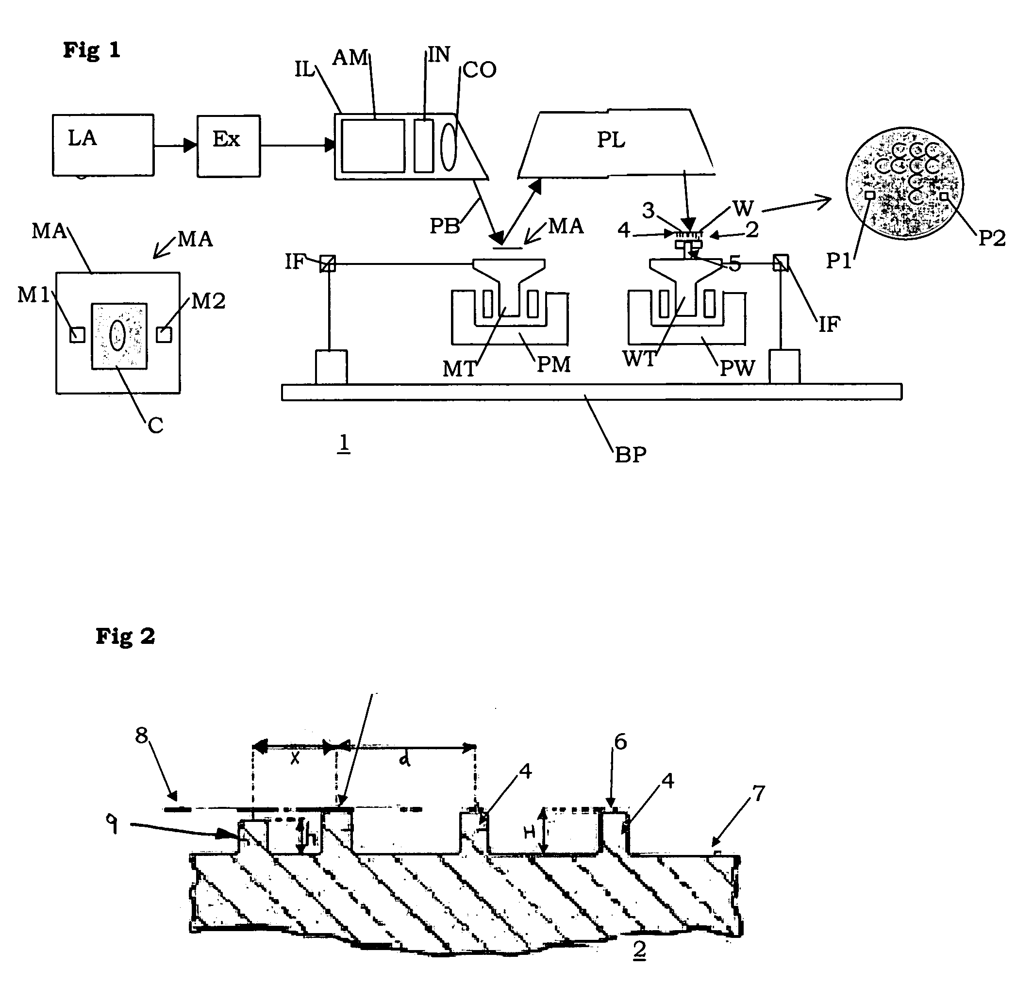
[0044]FIG. 1 schematically depicts a lithographic projection apparatus 1 according to a particular embodiment of the invention. The apparatus comprises:

[0045]a radiation system Ex, IL, for supplying a projection beam PB of radiation (e.g. light in the deep ultraviolet region). In this particular case, the radiation system also comprises a radiation source LA;

[0046]a first object table (mask table) MT provided with a mask holder for holding a mask MA (e.g. a reticle), and connected to first positioning devices PM for accurately positioning the mask with respect to item PL;

[0047]a second object table (substrate table) WT provided with a substrate holder 2 for holding a substrate 3, and connected to second positioning devices PW for accurately positioning the substrate with respect to item PL; and

[0048]a projection system (“lens”) PL for imaging an irradiated portion of the patterning device, illustrated in the form of the mask MA onto a target portion C (e.g. comprising one or more di...


PUM


Abstract

A lithographic projection apparatus including a radiation system for providing a projection beam of radiation; a support structure for supporting a patterning device, the patterning device serving to pattern the projection beam according to a desired pattern; a substrate holder having a plurality of protrusions, the extremities thereof defining a substantially flat plane of support for supporting a substantially flat substrate, the substrate holder provided with the ability to provide a pressing force for pressing the substrate against the extremities of the protrusions, the protrusions in an edge zone of the substrate holder arranged to provide a substantially flat overhanging of the substrate in relation to the pressing force of the pressing means; and a projection system for projecting the patterned beam onto a target portion of the substrate. The lithographic projection apparatus is characterized in that the protrusions in an off-edge zone of the substrate holder are distributed so as to provide a substantial equal supporting area for each protrusion of the plurality of protrusions, the supporting areas being defined by a Voronoi diagram distribution associated to the protrusions. The lithographic apparatus offers a substrate holder with a reduced overlay and focus error.

Description

[0001]The present application claims priority from EP Application No. 03076340.3 filed May 6, 2003, the content of which is incorporated herein by reference in its entirety.FIELD OF THE INVENTION[0002]The present invention relates to a lithographic apparatus. The present invention further relates to a substrate holder. The present invention further relates to a method of manufacturing.[0003]The present invention further relates to a lithographic projection apparatus comprising a radiation system for providing a projection beam of radiation; a support structure for supporting patterning devices, the patterning devices serving to pattern the projection beam according to a desired pattern; a substrate holder comprising a plurality of protrusions, the extremities thereof defining a substantially flat plane of support for supporting a substantially flat substrate, said substrate holder provided with a clamp to provide a pressing force for pressing the substrate against the extremities of...

Claims


Application Information

Patent Timeline
IPC IPC(8): G03B27/42B25B11/00G03B27/58G03B27/60G03F7/20H01L21/027H01L21/683
CPCG03F7/70783G03F7/707H01L21/67288H01L22/12
Inventor ZAAL, KOEN JACOBUS JOHANNES MARIAVAN EMPEL, TJARKO ADRIAAN RUDOLFOTTENS, JOOST JEROEN
Owner ASML NETHERLANDS BV
Why Eureka
Try Eureka