Eureka AIR delivers breakthrough ideas for toughest innovation challenges, trusted by R&D personnel around the world.

Fiber optic cable sensor for movable objects

a fiber optic cable and sensor technology, applied in the field of electronic intrusion detection systems, can solve the problems of no interior intrusion detection systems that work in spark sensitive rooms, system bulkiness, high cost, etc., and achieve the effect of improving the field of security systems

Active Publication Date: 2006-09-19
GIOTTO FR +4
View PDF2 Cites 12 Cited by
  • Summary
  • Abstract
  • Description
  • Claims
  • Application Information

AI Technical Summary

Benefits of technology

"The present invention is an apparatus that can detect when someone tries to tamper with an object, such as a manhole system or a work of art. It uses a fiber optic cable and a special portion of the object that cooperates with the cable to maintain it in a non-attenuated state. When the object is tampered with, the special portion no longer cooperates with the cable, creating a microbend that can be easily detected. This invention improves security systems and helps to protect against unauthorized access or theft."

Problems solved by technology

There are presently no interior intrusion detection systems that work for spark sensitive rooms such as those at oil refineries and others at power plants.
The known systems for these applications include an electronic signal that can ignite the contents of the room, and thus cause an explosion.
Once again this type of system will not work inside of a spark sensitive room for the aforementioned reasons.
These systems are bulky, expensive and highly noticeable.
These system also are tedious for many applications because much cabling is required to transmit signals indicative of an intrusion attempt.
Further, this cabling is easily corrupted making the entire system suspect to tamper.
If wireless links were to be used, the reliability of the system is constantly in jeopardy because of the inherent unreliable nature of the wireless technology.
An illustration of this is the common occurrence that interference from external sources causes disruption to wireless communications.
It is noticeable that these antennas sometimes become unreliable during storms.
Additionally, much expensive equipment and installation is required for wireless communications.
Each of these methods are costly and laborious.
These systems are expensive and suspect to tampering.

Method used


Image

  • Fiber optic cable sensor for movable objects
  • Fiber optic cable sensor for movable objects
  • Fiber optic cable sensor for movable objects

Examples


Embodiment Construction

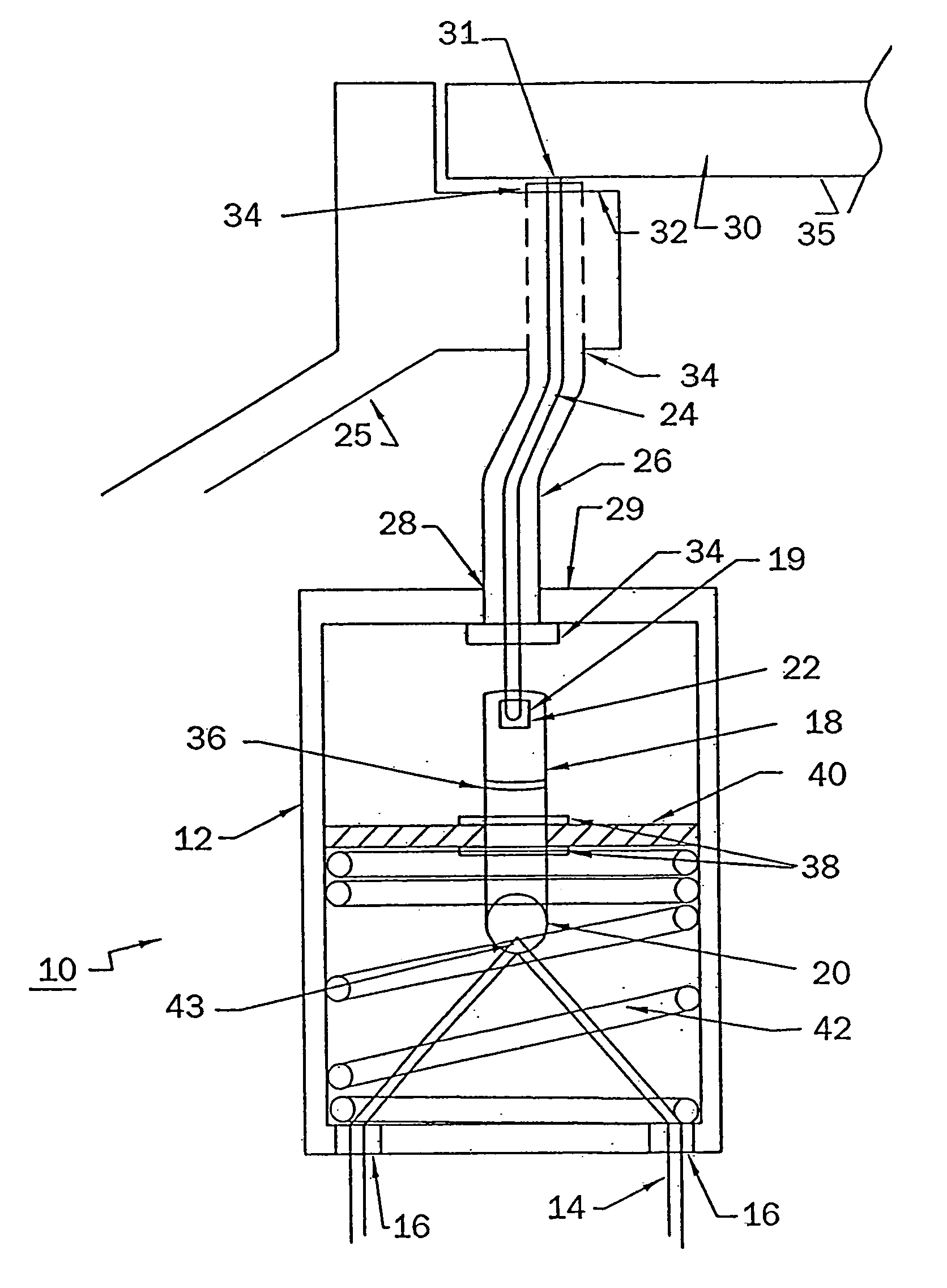
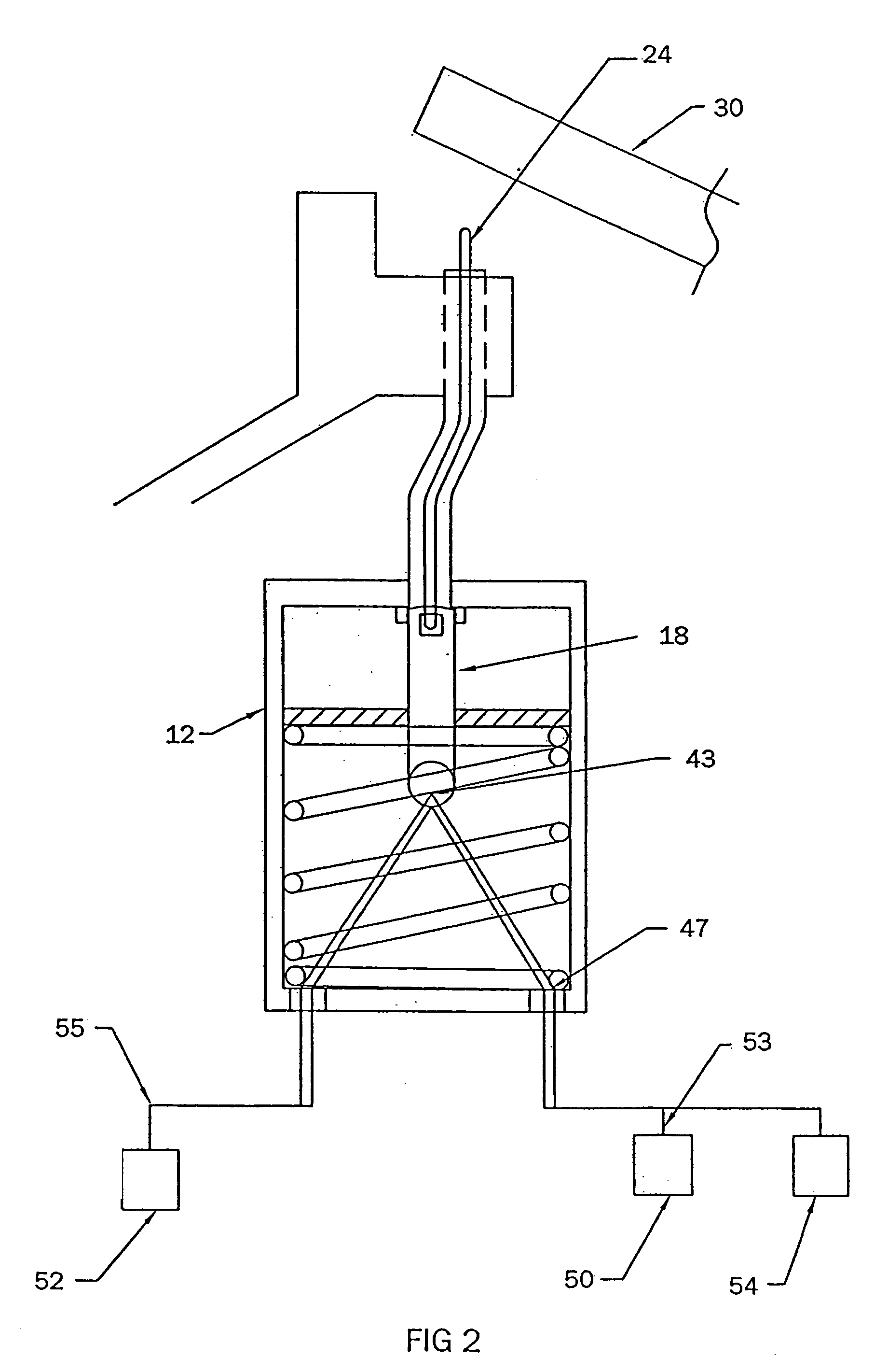
[0031]Referring now to FIGS. 1 and 2, a fiber optic cable sensor 10 in accordance with a preferred embodiment of the present invention includes a cable housing 12 mounted adjacent to an interior manhole wall 25. A fiber optic cable 14 runs through a pair of openings 16 disposed through the cable housing 12. For an entire manhole system it is desirable to install a cable housing 12 of the present invention adjacent to each individual manhole cover 30 and run a single fiber optic cable 14 through each individual cable housing 12. Thus, each manhole cover 30 of the system would be pre-assigned a specific location or length along the fiber optic cable 14, the reasons of which will become apparent with further reading.

[0032]A push / pull cable 24 extends through an opening 28 located at the top 29 of the cable housing 12 and contacts a bottom surface 31 of the manhole cover 30 which rests on an annular rim 32. In the embodiment shown in FIGS. 1 and 2, the push / pull cable24 is routed within...


PUM


Abstract

There is provided an apparatus that determines the location of an impermissible tamper on an object, such as an impermissible attempt to gain access to a manhole system or an attempt to steal a work of art, includes a housing disposed adjacently to the object. A fiber optic cable runs through the housing. The object includes a portion that cooperates with internal components of the housing to maintain the fiber optic cable in a non-attenuated state. Upon the impermissible tamper, that portion of the object no longer cooperates with the internal components of the housing. An elastic force internal to the housing cooperates with more internal housing components to create a microbend to the fiber optic cable. Using known optical time domain reflectometer technology, the location of the microbend along the fiber optic cable is readily discerned.

Description

FIELD OF THE INVENTION[0001]The present invention relates generally to the field of electronic intrusion sensors and, more particularly, to a fiber optic cable based sensor system that locates an impermissible movement of an object to help prevent theft or terrorism.BACKGROUND OF THE INVENTION[0002]There are many sensor systems that indicate the location of an intrusion attempt into a secure location or an attempt to steal a secure asset. For example, a door leading to a secure area might be rigged with a tamper switch that automatically relays a signal to a multiplexer and then onward to a de-multiplexer where the location of the intrusion is determined.[0003]There are presently no interior intrusion detection systems that work for spark sensitive rooms such as those at oil refineries and others at power plants. The known systems for these applications include an electronic signal that can ignite the contents of the room, and thus cause an explosion.[0004]Other types of systems inc...

Claims


Application Information

Patent Timeline
Patent Type & Authority Patents(United States)
IPC IPC(8): G08B17/02
CPCG08B13/1481
Inventor GIOTTO, FRANKHISERT, JAMESWERTZ, RAYMOND JOSEPHSITLER, BENJAMIN LEEKIRSHTEIN, MURRAY JOSEPH SELWYN
Owner GIOTTO FR
Why Eureka
Eureka Blog
Learn More