Battery mechanism

a battery pack and mechanism technology, applied in the field of battery pack mechanisms, can solve the problems of inherently dangerous high-voltage battery packs, severe injury or even death of personnel,

Inactive Publication Date: 2006-09-19
THE UNITED STATES OF AMERICA AS REPRESENTED BY THE SECRETARY OF THE NAVY
View PDF7 Cites 12 Cited by
  • Summary
  • Abstract
  • Description
  • Claims
  • Application Information

AI Technical Summary

Benefits of technology

[0005]In another embodiment of the invention, a method includes sliding battery packs over rods of a mounting plate and over a rod-shaped switching mechanism that is fixably mounted to the mounting plate. The battery assemblies each have holes corresponding to and aligning with the rods and the rod-shaped switching mechanism. A mounting bracket is fastened over the battery assemblies to the mounting plate. The ro

Problems solved by technology

Such high-voltage battery packs are inherently dangerous, however.
Incorrect installation or assembly of the battery packs, or defective battery packs, can potentially severely injure or even kill personnel.

Method used


Image

  • Battery mechanism
  • Battery mechanism
  • Battery mechanism

Examples


Embodiment Construction

[0018]In the following detailed description of exemplary embodiments of the invention, reference is made to the accompanying drawings that form a part hereof, and in which is shown by way of illustration specific exemplary embodiments in which the invention may be practiced. These embodiments are described in sufficient detail to enable those skilled in the art to practice the invention. Other embodiments may be utilized, and logical, mechanical, and other changes may be made without departing from the spirit or scope of the present invention. The following detailed description is, therefore, not to be taken in a limiting sense, and the scope of the present invention is defined only by the appended claims.

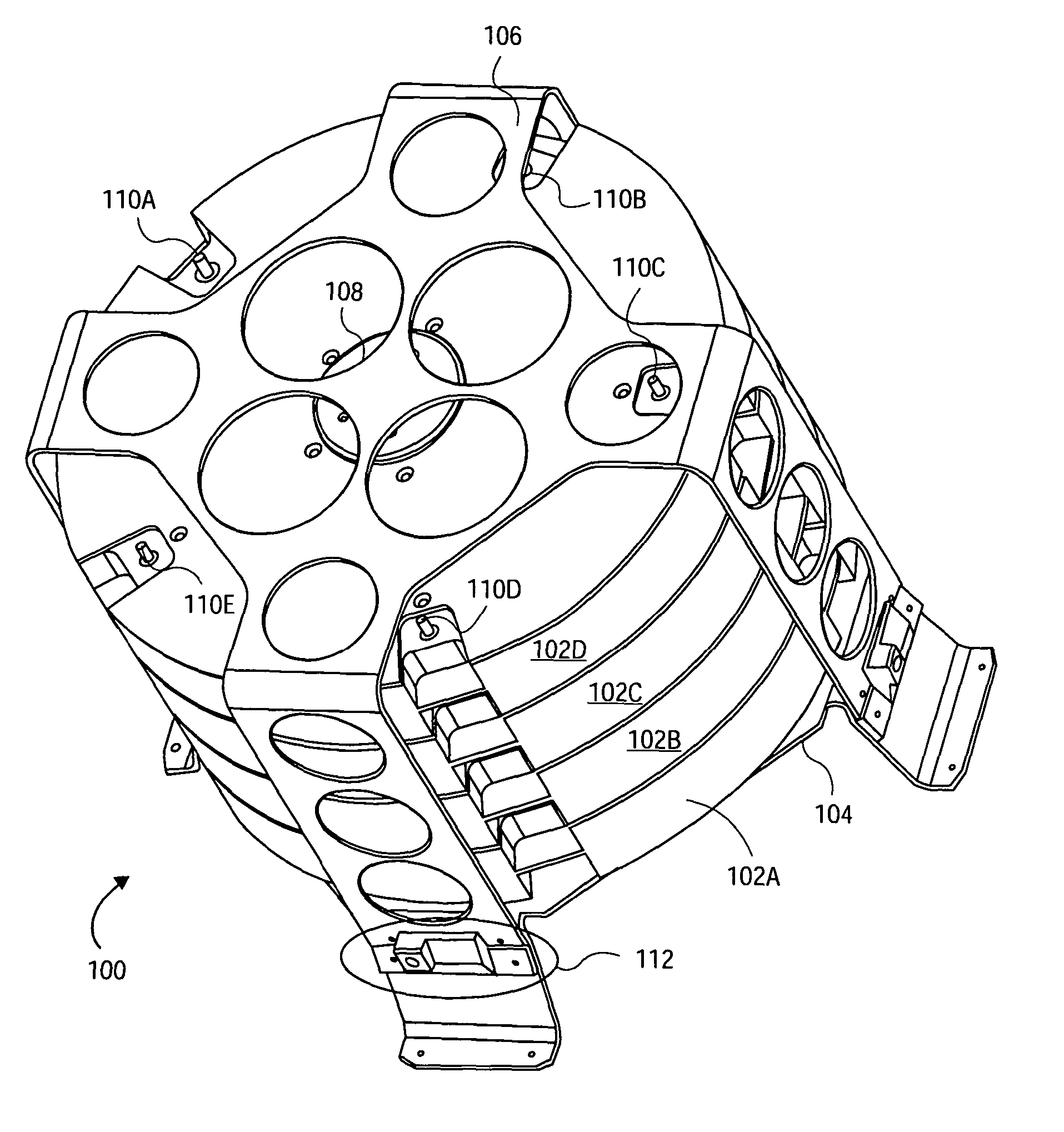
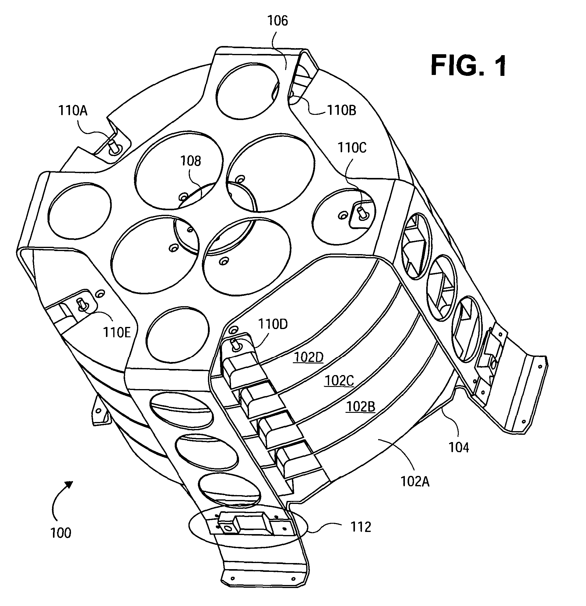
[0019]FIG. 1 shows a perspective view of a battery mechanism 100, according to an embodiment of the invention. A number of battery assemblies 102A, 102B, 102C, and 102D, collectively referred to as the battery assemblies 102 are removably mounted on rods 110A, 110B, 110C, 110D, and...


PUM


Abstract

A battery mechanism is disclosed. The battery mechanism in one embodiment includes battery assemblies, a switching mechanism, and an actuating mechanism. The battery assemblies are removably mounted to the switching mechanism. The switching mechanism has a non-energized position in which the battery assemblies are electrically disconnected from the switching mechanism. The switching mechanism also has an energized position in which the battery assemblies are electrically connected to the switching mechanism. The actuating mechanism is connected to the switching mechanism, and switches the switching mechanism between the non-energized and the energized positions. The actuating mechanism preferably is activated remotely, improving personnel safety. The number and make-up of the battery assemblies may be varied to provide for different voltages.

Description

FIELD OF THE INVENTION[0001]This invention relates generally to battery mechanisms, and more particularly to such mechanisms that preferably can safely, reliably, and remotely combine multiple battery assemblies.BACKGROUND OF THE INVENTION[0002]High-powered electrical devices at least occasionally require portable operation. This means that the devices must be able to be used off battery power. Such high-powered electrical devices include those used in pulsed power systems, which may find applicability in both military and non-military scenarios. The high voltage needed to power the electrical devices means that battery packs which power such electrical devices must themselves be able to provide high voltage. Such high-voltage battery packs are inherently dangerous, however. Incorrect installation or assembly of the battery packs, or defective battery packs, can potentially severely injure or even kill personnel. For these and other reasons, therefore, there is a need for the presen...

Claims


Application Information

Patent Timeline
IPC IPC(8): H01M2/10H01M10/00H01M6/00H01M6/42H01M6/46H01M6/44H01M10/42H01M50/574
CPCH01M2/202H01M10/4207H01M6/44H01M2/34Y02E60/10H01M50/574
Inventor SHARROW, JOSEPH F.SOLOMON, KURT W.PETERKIN, FRANK E.BERNARDES, JACK S.HANKLA, BRIAN J.
Owner THE UNITED STATES OF AMERICA AS REPRESENTED BY THE SECRETARY OF THE NAVY
Why Eureka
Try Eureka