Distributed feedback semiconductor laser

a semiconductor laser and distributed feedback technology, applied in the field of semiconductor lasers, can solve the problems of synergistic rise of oscillator threshold values, and achieve the effect of large coupling coefficient and increased light and diffraction grating coupling coefficien

Inactive Publication Date: 2006-09-12
FUJITSU LTD
View PDF4 Cites 0 Cited by
  • Summary
  • Abstract
  • Description
  • Claims
  • Application Information

AI Technical Summary

Benefits of technology

[0017]An object of this invention is to provide a TTG-DFB laser capable of maintaining a proper coupling coefficient and having good characteristics as a communication light source.
[0019]Light generated in the active layer is confined mainly in the lamination structure from the active layer to the tuning layer. Because the diffraction grating layer is disposed between the active layer and tuning layer, a coupling coefficient between light and diffraction grating can be raised. A large coupling coefficient can be maintained even if the optical electric field is deviated toward the active layer or tuning layer.

Problems solved by technology

Furthermore, because a loss by free carrier absorption increases, the oscillation threshold value rises synergistically.

Method used


Image

  • Distributed feedback semiconductor laser
  • Distributed feedback semiconductor laser
  • Distributed feedback semiconductor laser

Examples


Embodiment Construction

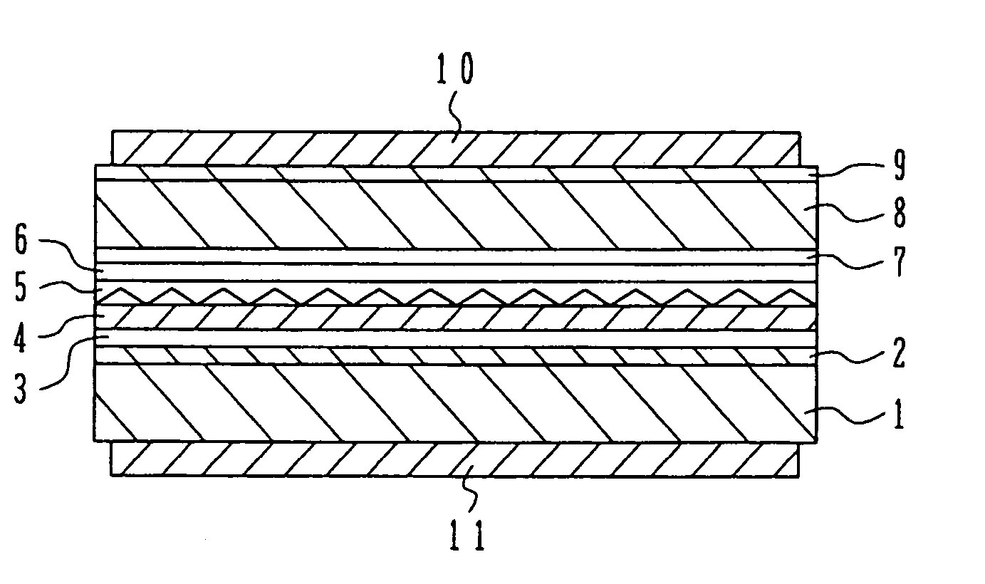
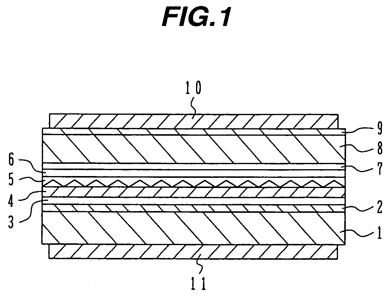
[0024]FIG. 1 is a cross sectional view of a TTG-DFB laser along a direction (light propagation direction) parallel to the longitudinal direction of an optical resonator, according to an embodiment of the invention. On a substrate 1 made of p-type InP, a buffer layer of p-type InP having a thickness of 1 μm is formed. A tuning layer 3, an intermediate layer 4, a diffraction grating layer 5 and a multiple quantum well active layer 6 are sequentially stacked in this order on the buffer layer 2. The substrate 1 and the buffer layer 2 serve as a clad layer.

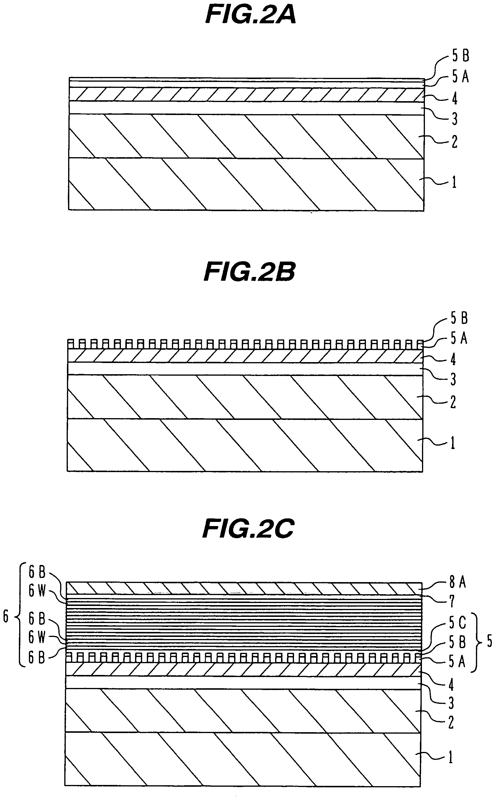
[0025]The tuning layer 3 is made of undoped Ga0.283In0.717As0.611P0.389 and has a thickness of 0.28 μm. The intermediate layer 4 is made of n-type InP and has a thickness of 0.11 μm. The diffraction grating layer 5 has a structure such that a diffraction grating made of n-type Ga0.217In0.783As0.472P0.528 is buried in the n-type JnP layer. The detailed structures of this layer will be later described.

[0026]The multiple quantum well acti...


PUM


Abstract

A tuning layer is disposed spaced by some distance apart from an active layer in a thickness direction, the tuning layer having a transition wavelength shorter than a wavelength of light radiated from the active layer. A diffraction grating layer is disposed between the active layer and tuning layer, a refractive index of the diffraction grating layer being periodically changed along an optical resonator direction. A first electrode supplies the active layer with current. A second electrode supplies the tuning layer with current independently from the current to be supplied to the active layer. A TTG-DFB laser is provided which can maintain a proper coupling coefficient and has characteristics suitable for application to communication light sources.

Description

CROSS REFERENCE TO RELATED APPLICATION[0001]This application is based on and claims priority of Japanese Patent Application No. 2003-28555 filed on Feb. 5, 2003, the entire contents of which are incorporated herein by reference.BACKGROUND OF THE INVENTION[0002]A) Field of the Invention[0003]The present invention relates to a semiconductor laser, and more particularly to a tunable twin-guide distributed feedback (TTG-DFB) type laser.[0004]B) Description of the Related Art[0005]Present backbone transmission systems for large capacity optical communication networks utilize wavelength division multiplexing (WDM) which can increase the capacity of transmission by multiplexing optical signals on a wavelength axis. As the degree of multiplexing is made high, the number of semiconductor lasers to be used as light sources increases. Backup light sources are also required as many as or larger than that of semiconductor lasers, resulting in annoying stock management. Simplifying the management...

Claims


Application Information

Patent Timeline
Patent Type & Authority Patents(United States)
IPC IPC(8): H01S5/00H01S5/028H01S5/062H01S5/12H01S5/22H01S5/227H01S5/32H01S5/343
CPCB82Y20/00H01S5/06206H01S5/12H01S5/028H01S5/34373H01S5/2275H01S5/3211H01S5/3434H01S5/2226
Inventor SEKINE, NORIHIKO
Owner FUJITSU LTD
Why Eureka
Try Eureka