
Multi-phase clock signal generator and method having inherently unlimited frequency capability

a multi-phase clock signal and generator technology, applied in pulse automatic control, pulse technique, instruments, etc., can solve the problems of severely restricting the frequency range over which delay-lock loops can be used, and it is generally not practical to use a fixed timing circui

Inactive Publication Date: 2006-09-12
MICRON TECH INC
View PDF16 Cites 29 Cited by
  • Summary
  • Abstract
  • Description
  • Claims
  • Application Information

AI Technical Summary

Problems solved by technology

Unfortunately, the phase of the system clock signal is normally substantially the same as the phase of the write data signals.
Therefore, it is generally not practical to use a fixed timing circuit to generate a write data strobe signal from the internal clock signal.
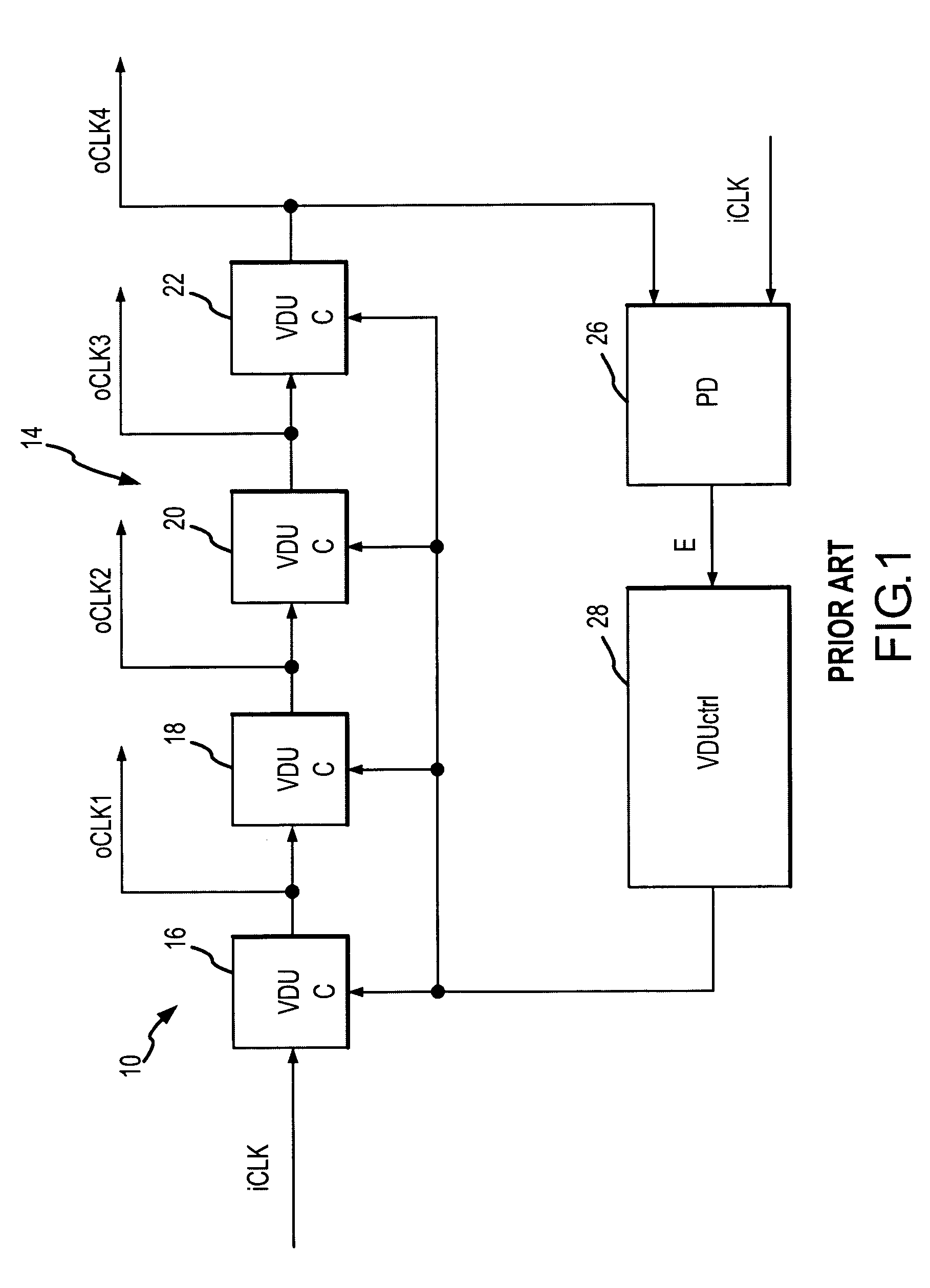
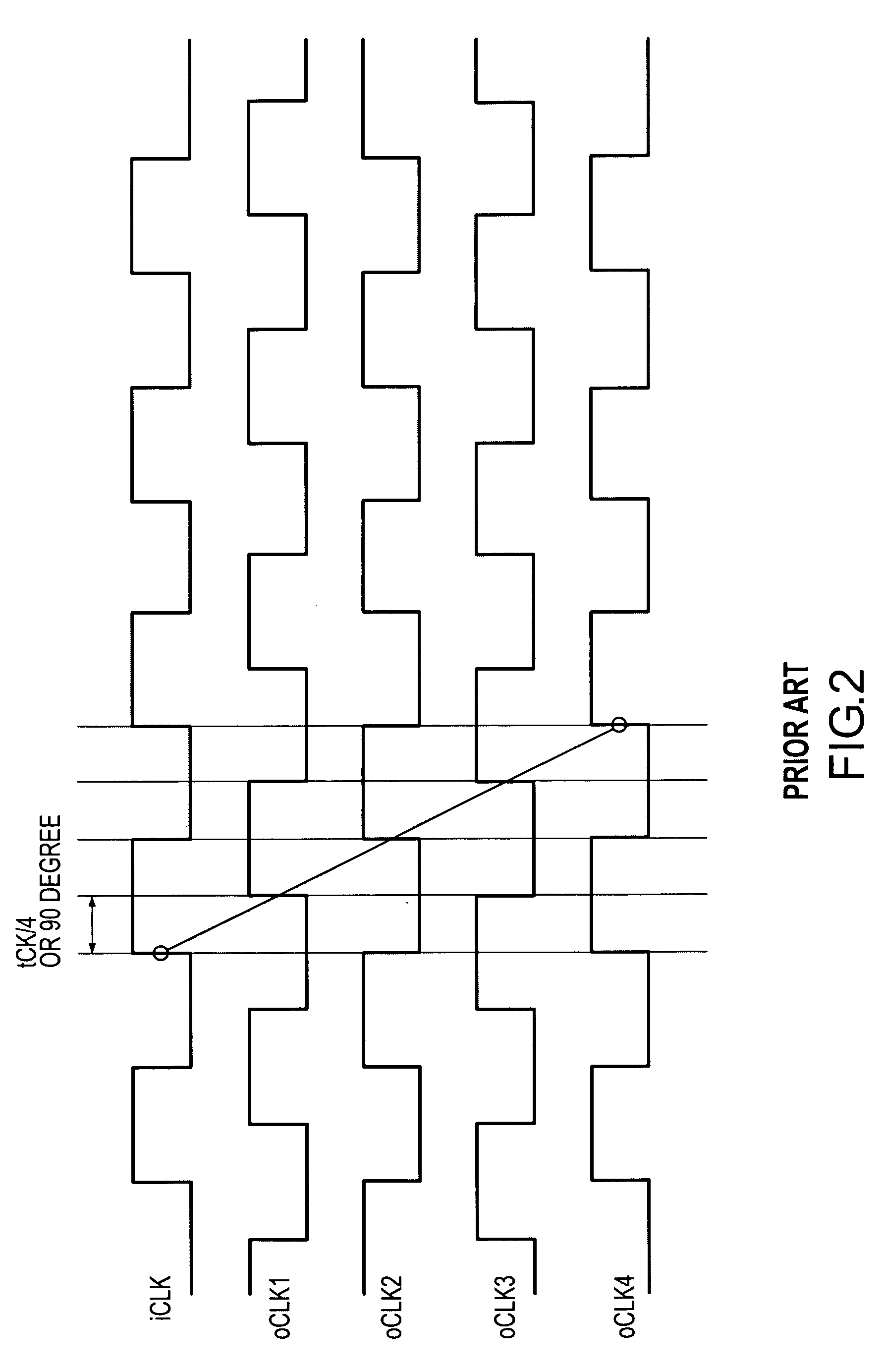
The fixed intrinsic delay of delay lines used in conventional delay-lock loops can therefore severely limit the frequency range over which delay-lock loops can be used.

Method used


Image

  • Multi-phase clock signal generator and method having inherently unlimited frequency capability
  • Multi-phase clock signal generator and method having inherently unlimited frequency capability
  • Multi-phase clock signal generator and method having inherently unlimited frequency capability

Examples


Embodiment Construction

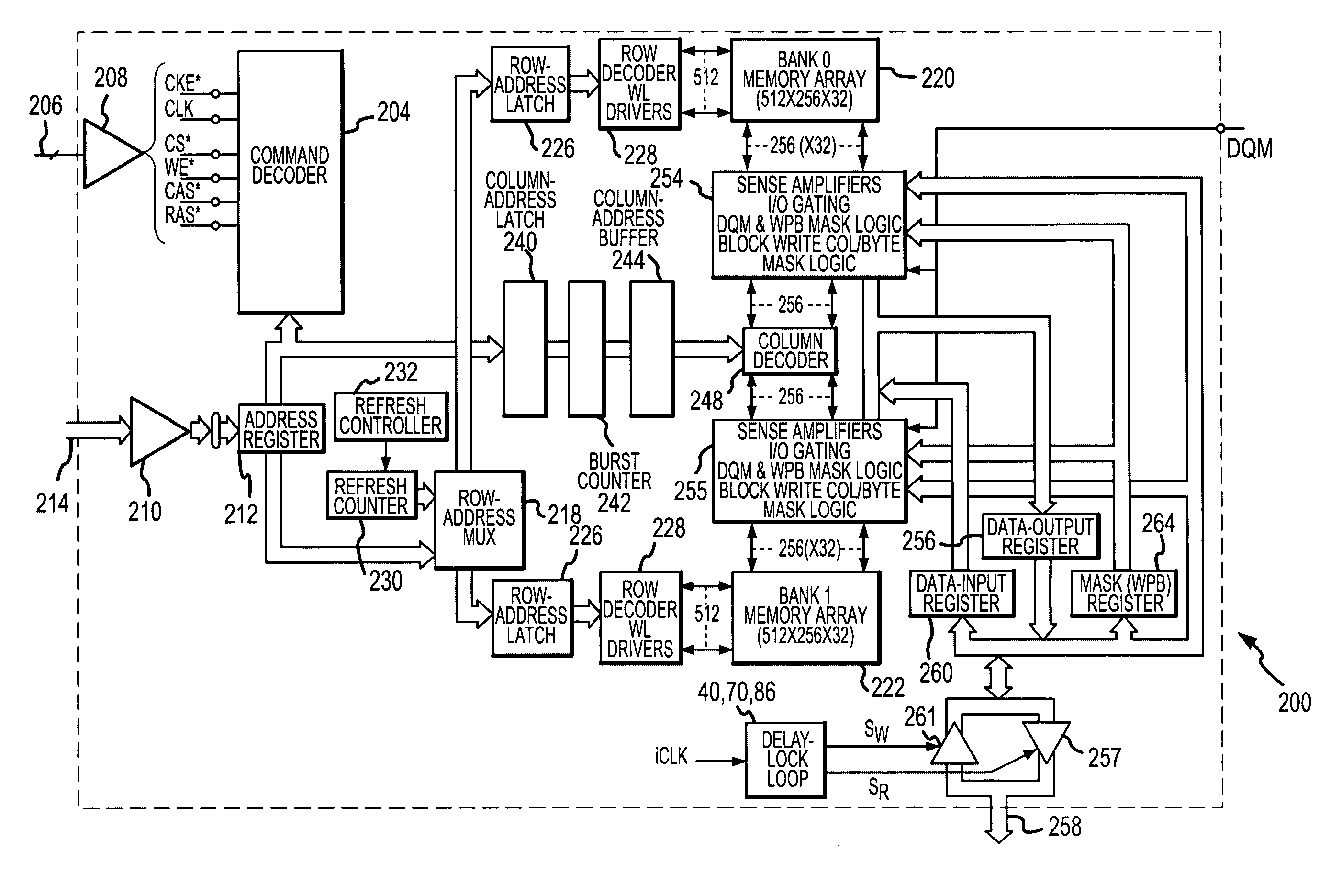
[0025]One embodiment of a delay-lock loop 40 for generating multi-phase clock signals is shown in FIG. 4. The delay-lock loop 40 receives the internal clock signal iCLK, and couples it through four paths 42, 44, 46, 48, which generate CLK1, CLK2, CLK3 and CLK4 signals, respectively. The first path 42 includes four series coupled VDUs 50a–d, which have their control input coupled to a voltage to provide a zero voltage-controlled delay DV. The VDUs 50a–d thus each provide a delay of only the intrinsic delay DI, and they are therefore designated by the nomenclature VDUi 50a–d. The final VDUi 50d outputs a CLK0 signal, which is delayed by four times the intrinsic delay of each VDUi 50a–d, i.e., 4DI.

[0026]The output from the next-to-last VDUi 50c is coupled through a VDU 54a, which generates a CLK1 signal. The VDU 54a delays the signal from the output of the VDUi 50c by the sum of the voltage controlled delay DV and the intrinsic delay DI. As a result, the CLK1 signal is delayed form the...


PUM


Abstract

A delay-lock loop includes several delay lines, all but the first of which is composed of at least one variable delay unit that provides a fixed delay and a variable delay. The first delay line is composed of a plurality of fixed delay units, but no variable delay units. The remaining delay lines are each composed of different numbers of variable delay units to provide respective clock signals having different phases, but they do not include any of the fixed delay units. The first and a last delay line receive an input clock signal. Each of the remaining delay lines are coupled to an output of one of the fixed delay units depending on the number of variable delay units in the delay line so that the resulting clock signals have all been delayed the same number of fixed delay periods.

Description

TECHNICAL FIELD[0001]This invention relates to clock generating systems and methods, and, more particularly, to a delay-lock loop and method for generating a multi-phased clock signal having a maximum operating frequency that is not limited by the minimum delay of voltage-controlled delay units used in the delay-lock loop.BACKGROUND OF THE INVENTION[0002]Periodic digital signals are commonly used in a variety of electronic devices. Probably the most common type of periodic digital signals are clock signals that are typically used to establish the timing of a digital signal or the timing at which an operation is performed on a digital signal. For example, data signals are typically coupled to and from memory devices, such as synchronous dynamic random access memory (“SDRAM”) devices, in synchronism with a clock or data strobe signal. More specifically, read data signals are typically coupled from a memory device in synchronism with a read data strobe signal. The read data strobe sign...

Claims


Application Information

Patent Timeline
Patent Type & Authority Patents(United States)
IPC IPC(8): G11C8/00
CPCG11C7/1072H03L7/0812H03L7/0805G11C7/222
Inventor LEE, SEONGHOON
Owner MICRON TECH INC
Learn More