Method of removing oxide film on a substrate with hydrogen and fluorine radicals
a technology of fluorine radicals and oxide films, applied in vacuum evaporation coatings, coatings, chemistry apparatuses and processes, etc., can solve the problems of organic substance, large amount of fluorine (f) atoms, and easy left-over residual substance after liquid evaporated
- Summary
- Abstract
- Description
- Claims
- Application Information
AI Technical Summary
Benefits of technology
Problems solved by technology
Method used
Image
Examples
first embodiment
[0077]FIGS. 3A and 3B are a top view and a sectional view, respectively, showing an apparatus 10 for processing a substrate according to a first embodiment of the present invention.
[0078]Referring to FIGS. 3A and 3B, the apparatus 10 for processing a substrate has a processing vessel 11 that is provided with a vacuation port 11A at an end thereof. A mount 12 that retains a substrate W that is to be processed is provided in the processing vessel 11.
[0079]An inner processing vessel 11B made of quartz glass is formed inside the processing vessel 11. A remote plasma source 13 is provided at another end of the processing vessel 11.
[0080]Hydrogen gas is provided to the remote plasma source 13 together with inert gas such as argon Ar. Hydrogen radicals H* are generated by exciting the hydrogen gas at a high frequency of 400 kHz, for example. The generated hydrogen radicals H* flow in the quartz processing vessel 11B along the surface of the substrate W on the mount 12 to the vacuation port...
second embodiment
[0097]FIG. 6 is a schematic diagram showing a gas providing system used for an apparatus for processing a substrate according to a second embodiment of the present invention. The apparatus for processing a substrate according to this embodiment is substantially identical to the apparatus 10 for processing a substrate described above, and its description is omitted. In FIG. 6, elements that have been described above are referred to by the same reference numerals, and their description is omitted.
[0098]Referring to FIG. 6, according to this embodiment, a line 14m for providing water vapor (H2O) including valves 14M and 14N and a mass flow controller 140 is added to the gas providing system connected to the processing gas port 14.
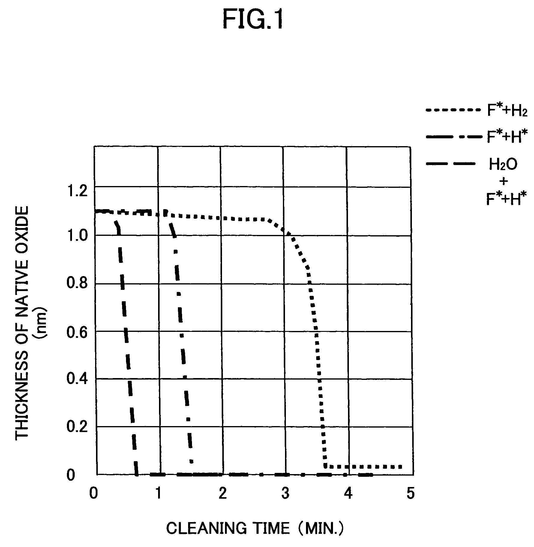
[0099]When native oxide is removed by hydrogen radicals H* and fluorine radicals F*, water vapor is provided to the processing vessel 11 as catalyst via the line 14m of the gas providing system shown in FIG. 6. The water vapor promotes the process of removing ...
third embodiment
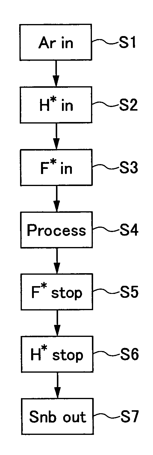
[0100]FIG. 7 is a flow chart showing a process for removing native oxide according to a third embodiment of the present invention that is performed by the apparatus 10 for processing a substrate shown in FIG. 3 and the gas providing system shown in FIG. 6.
[0101]Referring to FIG. 7, in step S11, Ar gas is introduced into the quartz processing vessel 11B via the line 14a, for example. Pressure in the quartz processing vessel 11B is maintained at 133 Pa, and temperature of the substrate W is maintained at 300° C.
[0102]In step S12, pressure in the processing vessel 11B is set in a range of 13.3 Pa–about 4 kPa thereby to generate plasma in the remote plasma source 13. Ar gas and hydrogen gas are provided to the remote plasma source 13 via the line 14a and the line 14b, respectively. The flow of Ar gas is maintained at 500 SCCM through 1000 SCCM, and the flow of hydrogen gas is maintained at 100 SCCM. A 1 kW, 400 kHz electric power is provided to the remote plasma source 13 thereby to gen...
PUM
| Property | Measurement | Unit |
|---|---|---|
| thick | aaaaa | aaaaa |
| thickness | aaaaa | aaaaa |
| frequency | aaaaa | aaaaa |
Abstract
Description
Claims
Application Information
 - R&D
- Intellectual Property
- Life Sciences
- Materials
- Tech Scout
- Unparalleled Data Quality
- Higher Quality Content
- 60% Fewer Hallucinations
Browse by: Latest US Patents, China's latest patents, Technical Efficacy Thesaurus, Application Domain, Technology Topic, Popular Technical Reports.
© 2025 PatSnap. All rights reserved.Legal|Privacy policy|Modern Slavery Act Transparency Statement|Sitemap|About US| Contact US: help@patsnap.com


