
Apparatus for transmitting RF signal in mobile communication terminal and method for controlling the same

a mobile communication terminal and antenna technology, applied in the direction of transmission monitoring, modulation, gain control, etc., can solve the problems of signal interference between the two signals, noise is greater, noise may occur, etc., to prevent the spiking of output power, maintain linearity and discontinuity of power level, and reduce noise

Active Publication Date: 2006-09-05
SAMSUNG ELECTRONICS CO LTD
View PDF3 Cites 2 Cited by
  • Summary
  • Abstract
  • Description
  • Claims
  • Application Information

AI Technical Summary

Benefits of technology

[0012]Therefore, the present invention has been made in view of the above problems, and it is an object of the present invention to provide an RF transmitter for satisfying a specification of a mobile communication system while simultaneously reducing noise, and a method for controlling the same.
[0013]It is another object of the present invention to provide an RF transmitter insensitive to a temperature variation that simultaneously reduces noise, and a method for controlling the same.
[0014]It is yet another object of the present invention to provide an RF transmitter for preventing an output power from spiking, and maintaining a linearity and discontinuity of a power level simultaneously with reducing noise, and a method for controlling the same.

Problems solved by technology

Noise is a greater problem in such a wireless communication system than a wired communication system because the data transmission is wirelessly performed.
The noise may occur due to limitations of a channel environment or a transmitter.
Therefore, in the case where a signal having a frequency similar to the raised frequency band is adjacent to the signal of the data to be transmitted, signal interference may occur between the two signals under the condition that two wireless terminals using two similar frequencies are adjacent to each other.
Since the data has a high frequency, noise may be caused by refraction and diffraction phenomena, and noise may be also caused by a time delay owing to a difference between transmission paths.
In the case of radio data transmission, besides the noise generated in the radio channel, noise is generated in a transmission device (i.e., a transmitter).
The noise generated in the transmitter occurs during signal step-up conversion or transmission amplification.
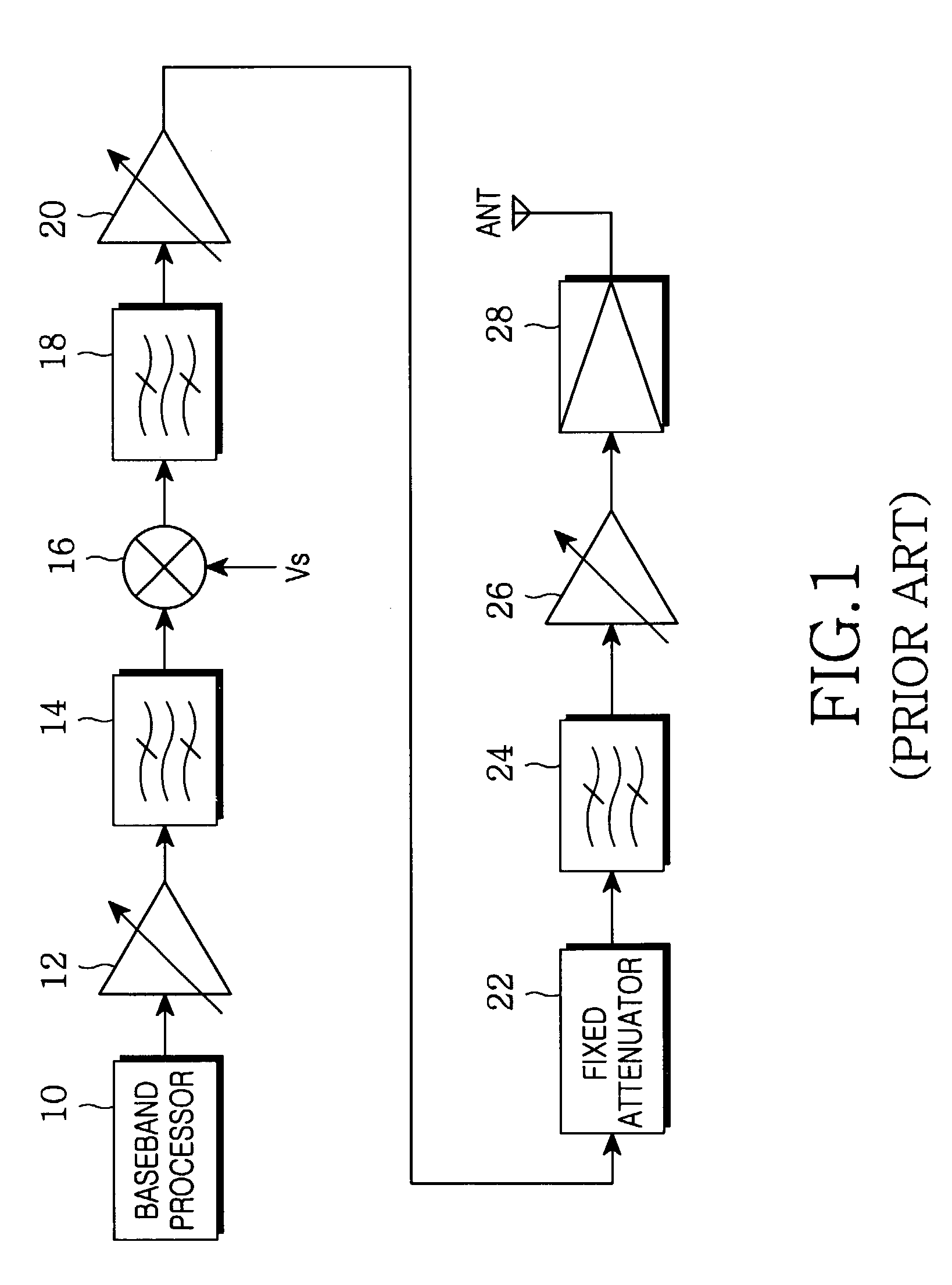
However, the RF transmitter of FIG. 1 has a disadvantage in that it degrades a level of input power in accordance with an ACPR of a maximum output power because the fixed attenuator 22's value is always fixed to a predetermined value.
Also, the RF transmitter of FIG. 1 has a further disadvantage in that it has a high power variation at a low temperature.
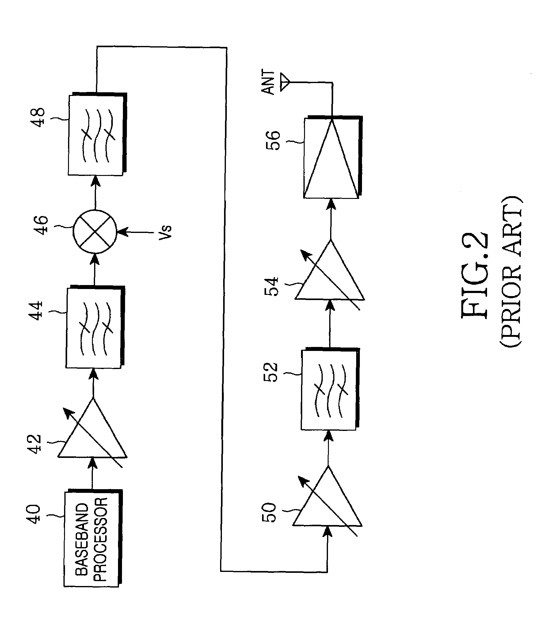
The drive amplifier 50 has an unavoidable discontinuity in the case of adjusting a power level because it adopts the step gain adjustment method.
As a result, in the case of measuring an RF signal such as a signal “open_loop_time_response”, the output power may suddenly rise or spike.
This may result in exceeding the power range required by an RF specification of a mobile communication terminal.

Method used


Image

  • Apparatus for transmitting RF signal in mobile communication terminal and method for controlling the same
  • Apparatus for transmitting RF signal in mobile communication terminal and method for controlling the same
  • Apparatus for transmitting RF signal in mobile communication terminal and method for controlling the same

Examples


Embodiment Construction

[0024]Preferred embodiments of the present invention will be described in detail with reference to the annexed drawings. In the drawings, the same or similar elements are denoted by the same reference numerals even though they are depicted in different drawings. In the following description, a detailed description of known functions and configurations incorporated herein will be omitted in order to focus on the subject matter of the present invention.

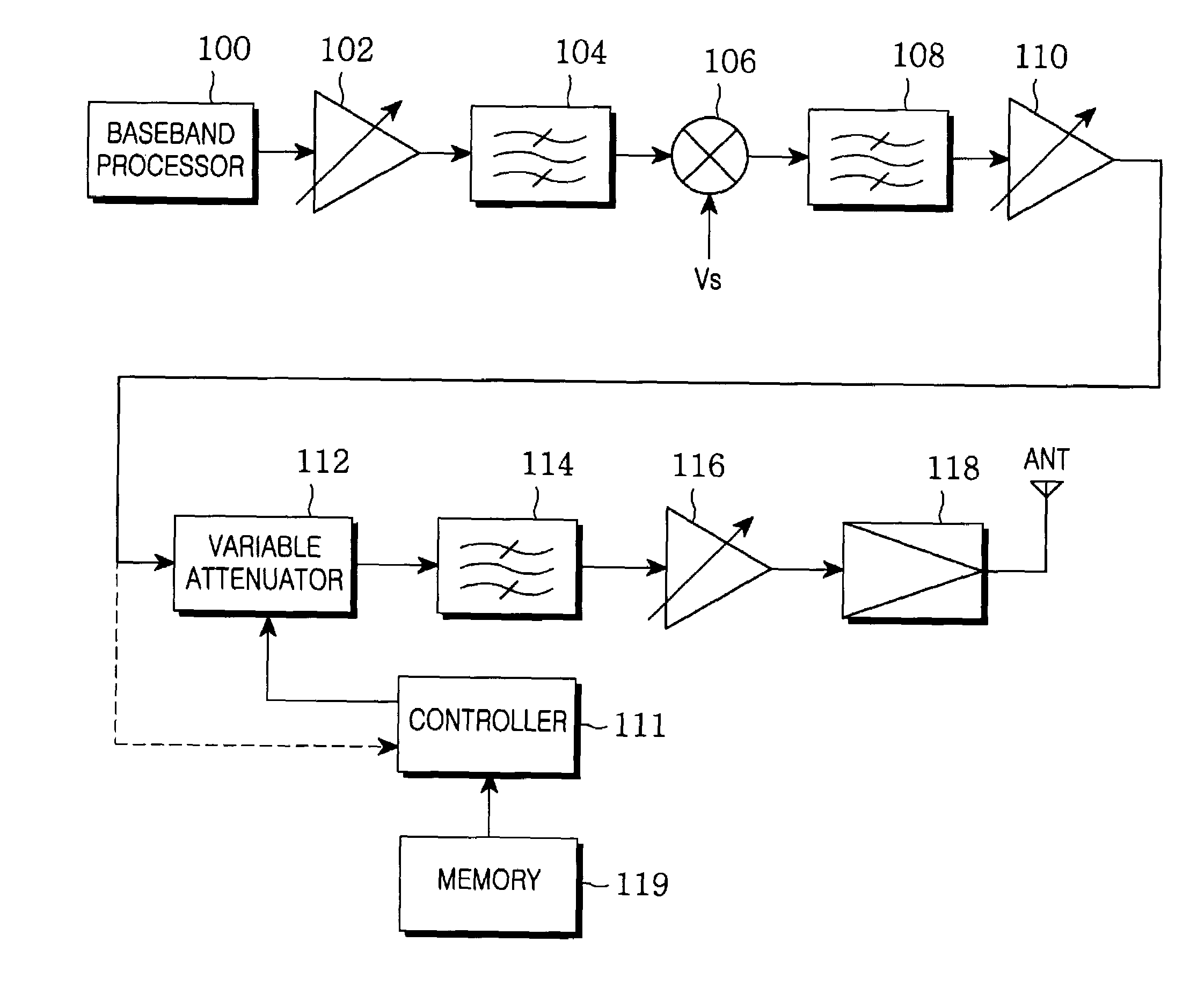
[0025]FIG. 3 is a view illustrating a block diagram of an RF transmitter for reducing noise in a mobile communication terminal in accordance with a preferred embodiment of the present invention. A block diagram of an RF transmitter of a mobile communication terminal and operations for each block will hereinafter be described with reference to FIG. 3.

[0026]Referring to FIG. 3, a baseband processor 100 converts baseband signals, i.e., data to be transmitted, into symbols. The baseband processor 100 can be implemented with a BBA (Base Band...


PUM


Abstract

An apparatus for transmitting an RF signal in a mobile communication terminal and a method for controlling the same. The apparatus is insensitive to temperature variation simultaneously with satisfying a specification of a mobile communication system, and reduces noise simultaneously with preventing output power from bounding. The apparatus includes a step-up converter for converting a signal to be transmitted into a signal of a transmission band; a reverse variable attenuator for performing high attenuation or low attenuation about an output signal of the step-up converter according to an attenuation control value; a transmission power processor for raising power of an output signal of the reverse variable attenuator to transmission power; and a controller for generating the attenuation control value used for performing high attenuation if the signal to be transmitted requires a low output power level, whereas performing low attenuation if the signal to be transmitted requires a high output power level.

Description

PRIORITY[0001]This application claims priority to an application entitled “APPARATUS FOR TRANSMITTING RF SIGNAL IN MOBILE COMMUNICATION TERMINAL AND METHOD FOR CONTROLLING THE SAME”, filed in the Korean Intellectual Property Office on Apr. 19, 2002 and assigned Serial No. 2002-21649, the contents of which are hereby incorporated by reference herein.BACKGROUND OF THE INVENTION[0002]1. Field of the Invention[0003]The present invention relates to an apparatus for processing signals in a mobile communication terminal and a method for controlling the same, and more particularly to an apparatus for processing RF (Radio Frequency) transmission signals in a mobile communication terminal and a method for controlling the same.[0004]2. Description of the Related Art[0005]Typically, since a mobile terminal and a base station are spaced apart from each other at a predetermined distance in a mobile communication system, they perform a transmission / reception operation on a predetermined frequency ...

Claims


Application Information

Patent Timeline
Patent Type & Authority Patents(United States)
IPC IPC(8): H04B1/02H04B7/26H03G3/30H04B1/04
CPCH04B1/04H03G3/3042H04B7/26
Inventor RHEEM, JAE-WOOK
Owner SAMSUNG ELECTRONICS CO LTD
Learn More