
Duplexer with extended functionality

a technology of duplexer and functionality, applied in the field of duplexer, can solve problems such as signal loss at the adaptation elements

Active Publication Date: 2006-09-05
SNAPTRACK
View PDF23 Cites 96 Cited by
  • Summary
  • Abstract
  • Description
  • Claims
  • Application Information

AI Technical Summary

Benefits of technology

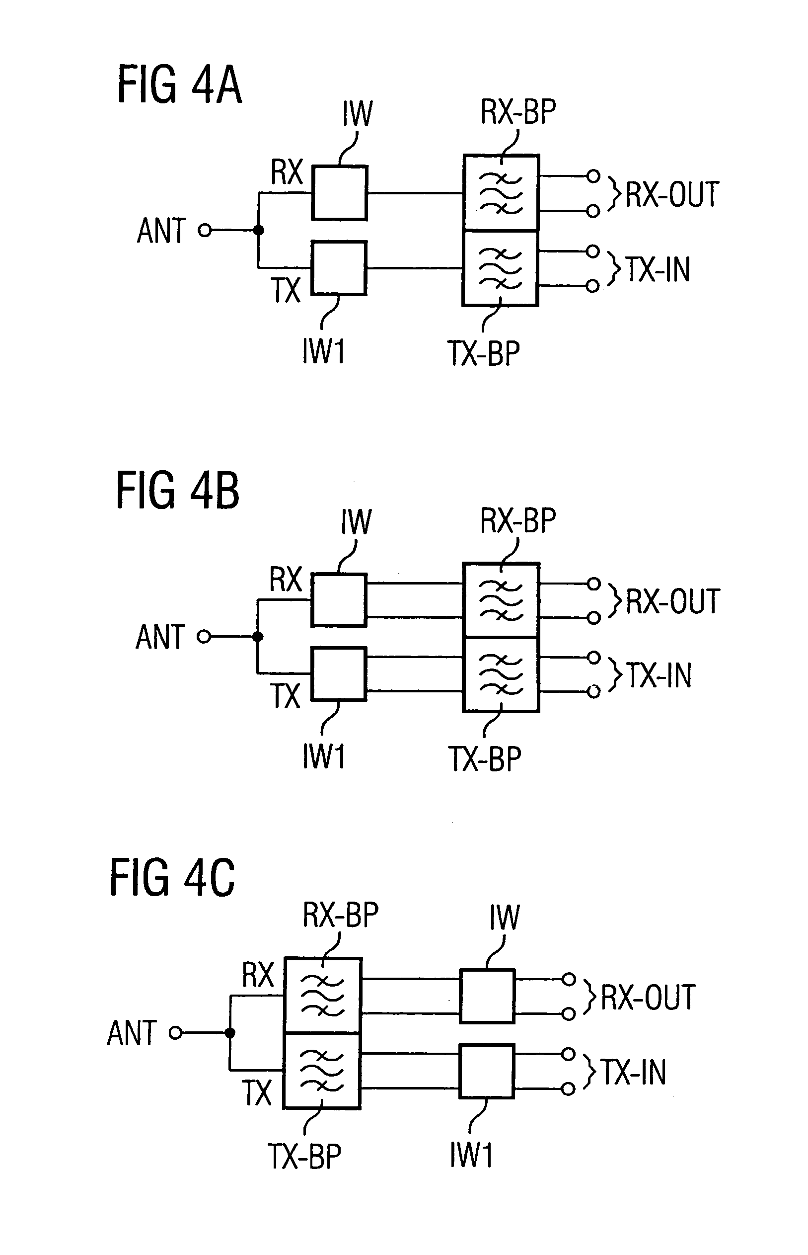
[0017]Unlike current duplexers, a duplexer according to the invention has the advantage that no intermediate stage, such as a balun or—in the case of impedances that differ between the duplexer and the corresponding amplifier—an impedance transformer, is required between the duplexer and the power amplifier that is pre-connected in the transmission path or the low-noise amplifier that is post-connected in the reception path.

Problems solved by technology

The circuit elements that are pre-connected and post-connected in relation to the duplexer form an interface to the duplexer, at which point, in the case of a sudden impedance jump, a portion of the energy of the signal is reflected, which is why an additional impedance adaptation of the stages is often required, and which results in signal losses at the adaptation elements.

Method used


Image

  • Duplexer with extended functionality
  • Duplexer with extended functionality
  • Duplexer with extended functionality

Examples


Embodiment Construction

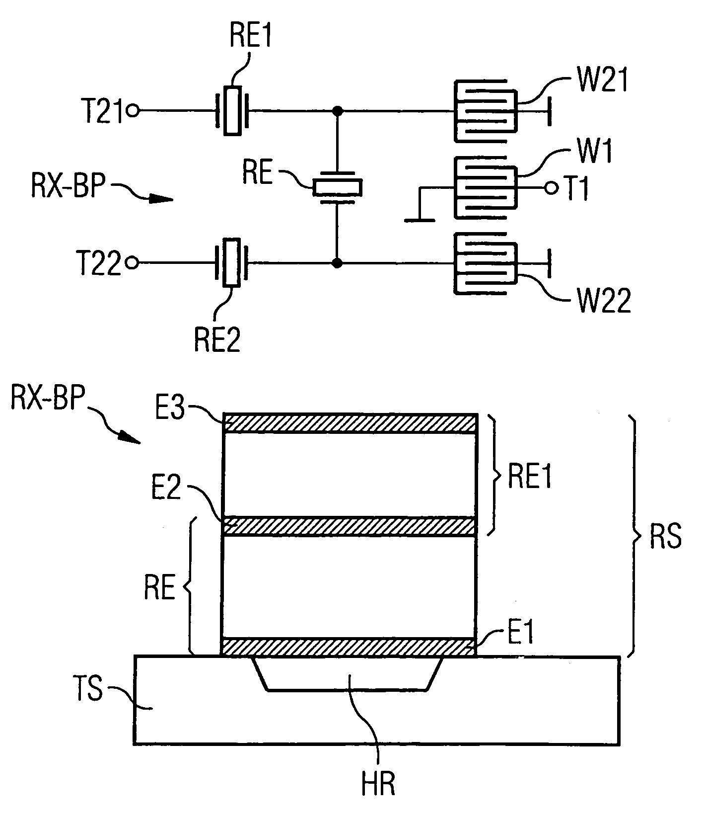
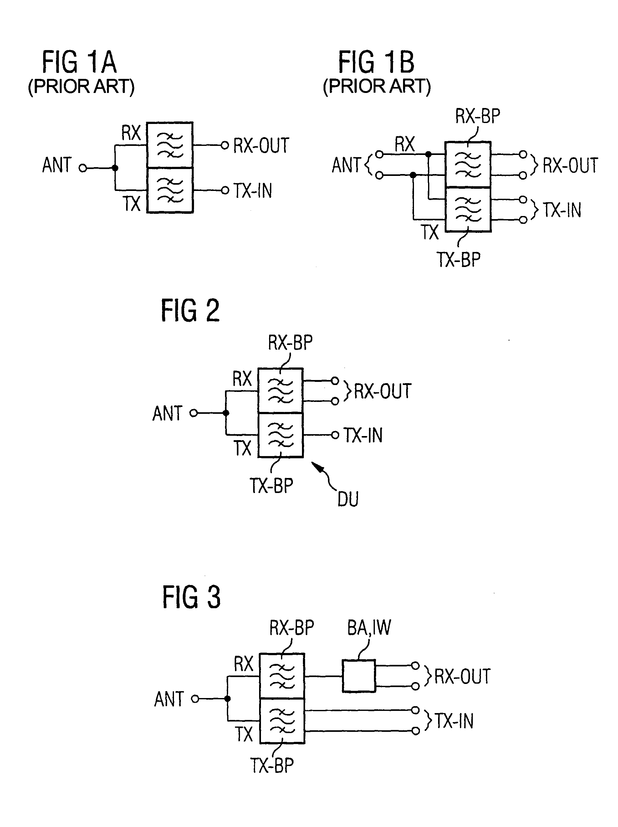
[0035]FIG. 2 shows a first variant of the duplexer DU according to the invention with an asymmetrically designed transmission input TX-IN. The duplexer has an asymmetrically designed antenna port ANT as well as parallel signal paths RX (reception path) and TX (transmission path), which are either directly connected at one end to the antenna port ANT or indirectly, through an adaptation circuit not illustrated here, and, at the opposite end, to another port (reception output RX-OUT of the reception path, the transmission input TX-In of the transmission path). A transmission bandpass filter TX-BP is arranged in the transmission path TX, and a reception bandpass filter is arranged in the reception path RX.

[0036]In this variant, the transmission input TX-IN is designed asymmetrically.

[0037]The reception output RX-out is designed symmetrically. The reception bandpass filter RX-BP is asymmetrical at the input (on the antenna's side), and symmetrical on the output side, and thus has a balu...


PUM


Abstract

A duplexer has an asymmetrical antenna port and a symmetrical reception output, and therefore can be interconnected (without any intermediate stages) to an amplifier with a differential input. A reception bandpass filter is arranged in the reception path of the duplexer. The reception bandpass filter can have the functionality of a balun. The transmission input of the duplexer can be designed symmetrically, in which case a transmission bandpass filter arranged in the transmission path should be designed symmetrically on the input side. The impedance of the antenna port of the duplexer can differ from the impedance of the reception output or the transmission input. No intermediate stages (such as a balun or—in cases of impedances that differ between the duplexer and its corresponding amplifier—an impedance transformer) are required between the duplexer and the amplifier that is interconnected (whether before or after) in the transmission or reception path.

Description

BACKGROUND OF THE INVENTION[0001]1. Field of the Invention[0002]This invention relates to a duplexer.[0003]2. Description of the Prior Art[0004]A duplexer serves the purpose of separating the transmitted and received signals in the frequency band of a communication system, such as in a mobile radio telephone standard that uses a frequency division duplex operation or a mixed frequency division / time division duplex operation. The frequency band of the communication system is divided into a transmission band and a reception band. A duplexer should ensure a lower insertion attenuation in the relevant passband, as well as a high insulation of the reception and transmission paths, i.e., a high suppression of a signal to be transmitted in one direction in the passband of the signal to be transmitted in the opposite direction.[0005]FIG. 1a schematically shows a known duplexer that has an antenna port ANT, a transmission input TX-IN and a reception output RX-OUT. The transmission input TX-I...

Claims


Application Information

Patent Timeline
IPC IPC(8): H03H9/70H03H9/72H03H7/42H03H7/46H03H9/00H03H9/58H04B1/40
CPCH03H9/0038H03H9/0095H03H9/0571H03H9/0576H03H9/725H03H9/587H03H9/589H03H9/706H03H9/72H03H9/584
Inventor SCHMIDHAMMER, EDGARTIKKA, PASI
Owner SNAPTRACK
Learn More