Small-spot spectrometry instrument with reduced polarization and multiple-element depolarizer therefor

a polarization and spectrometry technology, applied in the field of optical metrology systems, can solve the problems of low sensitivity, low sensitivity, and low sensitivity of depolarizing elements, and achieve the effects of reducing sensitivity, weakening birefringence, and high cos

Inactive Publication Date: 2006-08-29
TOKYO ELECTRON LTD
View PDF19 Cites 13 Cited by
  • Summary
  • Abstract
  • Description
  • Claims
  • Application Information

AI Technical Summary

Benefits of technology

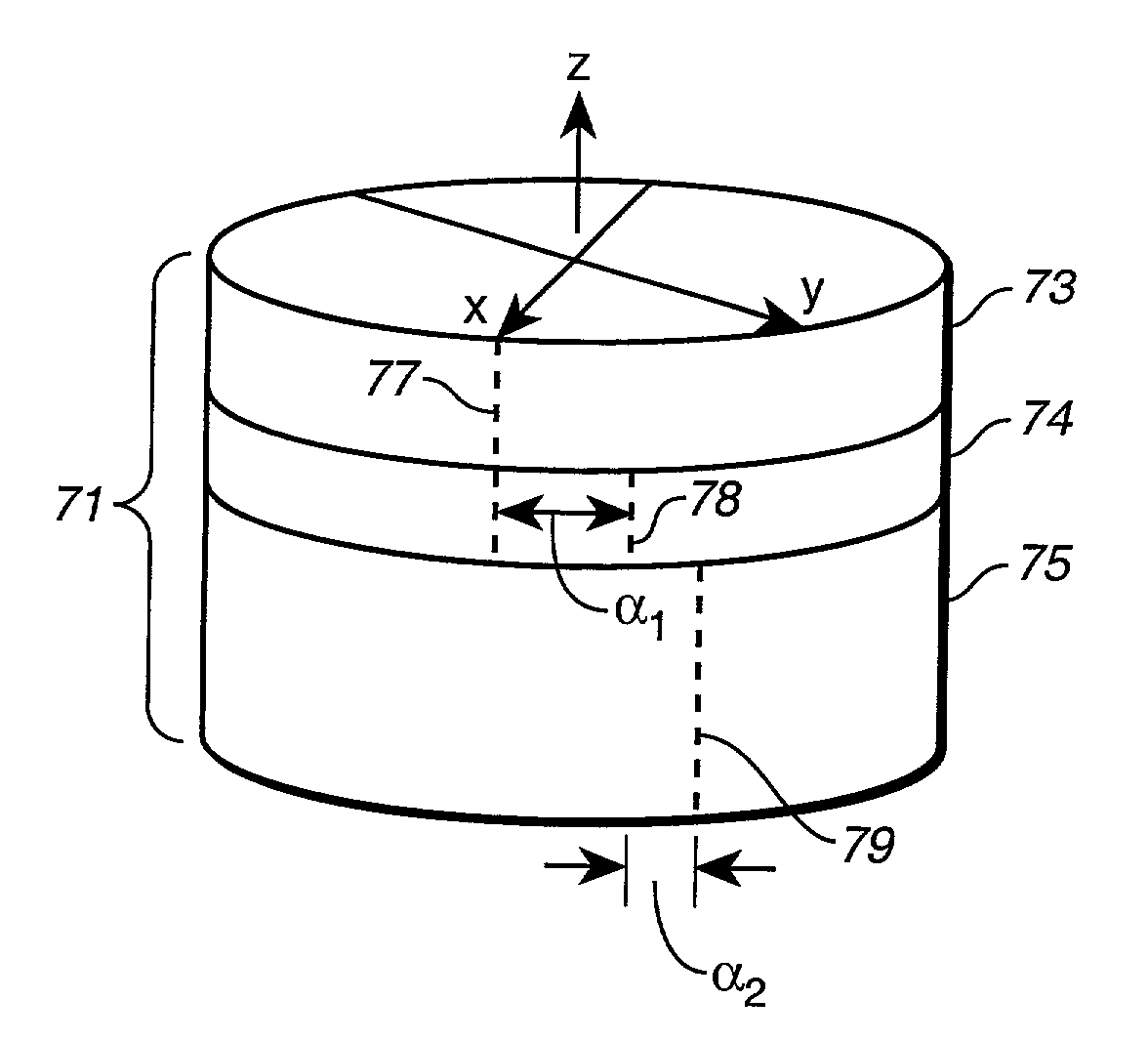
[0021]The depolarizers used in this invention do not vary the polarization spatially as wedge depolarizers do. Rather, they vary the polarization with wavelength. The sinusoidally perturbed spectrum that results can be removed by data processing techniques. If the depolarizer is made thick enough or made from a highly birefringent material, such as calcite, alpha barium borate or quartz, then the sinusoidal perturbation may be much narrower than the wavelength resolution of the instrument. In this case the perturbation would not be detectable and no processing would be required to remove it. The only disadvantage of using calcite for the depolarizer material is that it does not transmit as much UV light as alpha barium borate or quartz. Disadvantages of alpha barium borate are its high cost, weaker birefringence, and sensitivity to humidity. Quartz has even lower birefringence requiring very thick pieces to make effective depolarizers. The present invention is for an improved depolarizer, which aids in achieving the goal of “unpolarized” illumination and detection in a normal-incidence reflectometer. It allows a sample, even one that changes the state of polarization of light upon reflection, to be measured at an arbitrary rotation.

Problems solved by technology

The only disadvantage of using calcite for the depolarizer material is that it does not transmit as much UV light as alpha barium borate or quartz.
Disadvantages of alpha barium borate are its high cost, weaker birefringence, and sensitivity to humidity.

Method used


Image

  • Small-spot spectrometry instrument with reduced polarization and multiple-element depolarizer therefor
  • Small-spot spectrometry instrument with reduced polarization and multiple-element depolarizer therefor
  • Small-spot spectrometry instrument with reduced polarization and multiple-element depolarizer therefor

Examples


Embodiment Construction

[0031]With reference to FIG. 3, a spectrometry instrument 100 in accord with the present invention, to detect reflectivity at a spot of interest on sample 128, is seen to include a Lyot depolarizer 122. The instrument 100 in FIG. 3 is a near-normal incidence reflectometer. Illuminating light beam 104 from a light source (not shown) exits illumination fiber 102. Turn mirror 106 deflects the illuminating light beam 104 through collimator 108. Turn mirrors 110 and 112 direct the light through illumination aperture 114, and on to beam splitter 115. The beam splitter 115 is preferably a plate beam splitter, rather than a cube beamsplitter, to minimize ghost reflections. The beam splitter transmits portion 116 of the illumination beam and beam dump 118 absorbs it. Alternatively, a reference spectrometer could be positioned in place of beam dump 118 to measure the transmitted portion 116. (Or, such a reference spectrometer might be positioned instead to receive light temporarily diverted f...


PUM

PropertyMeasurementUnit
thickaaaaaaaaaa
anglesaaaaaaaaaa
thicknessesaaaaaaaaaa

Abstract

A small-spot imaging, spectrometry instrument for measuring properties of a sample has a polarization-scrambling element, such as a birefringent plate depolarizer, incorporated between the polarization-introducing components of the system, such as the beamsplitter, and the microscope objective of the system. The plate depolarizer varies polarization with wavelength, and may be a Lyot depolarizer with two plates, or a depolarizer with more than two plates (such as a three-plate depolarizer). Sinusoidal perturbation in the resulting measured spectrum can be removed by data processing techniques or, if the depolarizer is thick or highly birefringent, the perturbation may be narrower than the wavelength resolution of the instrument.

Description

CROSS-REFERENCE TO RELATED APPLICATIONS[0001]This application is a continuation-in-part of U.S. patent application Ser. No. 09 / 932,548, filed Aug. 17, 2001, which claims priority under 35 U.S.C. 119(e) from prior U.S. provisional application No. 60 / 226,396, filed Aug. 18, 2000. This application also claims priority under 35 U.S.C. 119(e) from U.S. provisional application No. 60 / 350,823, filed Jan. 18, 2002.TECHNICAL FIELD[0002]The present invention relates generally to optical metrology systems that measure optical characteristics of a sample in order to determine physical properties of interest of the sample. Systems having optical instruments that measure light scattered from a sample (whether by reflection or transmission) and which interpret the measured characteristics (e.g., by comparing with predictions of an optical model) to determine physical parameters of the sample (e.g., of grating-like structures on a silicon wafer) are of particular relevance. Relevant optical instrum...

Claims


Application Information

Patent Timeline
Patent Type & Authority Patents(United States)
IPC IPC(8): G02B5/30G02B27/28G01J3/10G01J3/02G01J3/28G01N21/31G01N21/956
CPCG01J3/02G01J3/0224G01J3/0243G01N21/21G01N21/31G03F7/70991G02B27/28G02B27/286G02B27/288G03F7/70625G01N21/956G01J3/28G01N2021/213G02B5/3083
Inventor NORTON, ADAM E.JOHNSON, KENNETH C.STANKE, FRED E.
Owner TOKYO ELECTRON LTD
Why Eureka
Try Eureka