
Elevator landing door broken chain safety device

a technology for safety devices and elevator landing doors, which is applied in the direction of wing fasteners, door/window fittings, wing suspension devices, etc., can solve the problems of unrecognised wear, personal injury and/or property damage to objects below the panel, and the reaction time of the panel itsel

Active Publication Date: 2006-08-29
PEELLE COMPANY LTD THE
View PDF23 Cites 19 Cited by
  • Summary
  • Abstract
  • Description
  • Claims
  • Application Information

AI Technical Summary

Benefits of technology

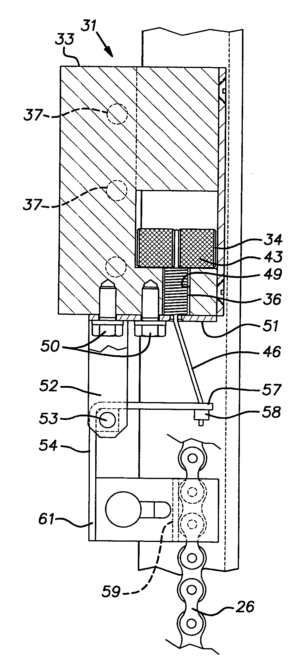
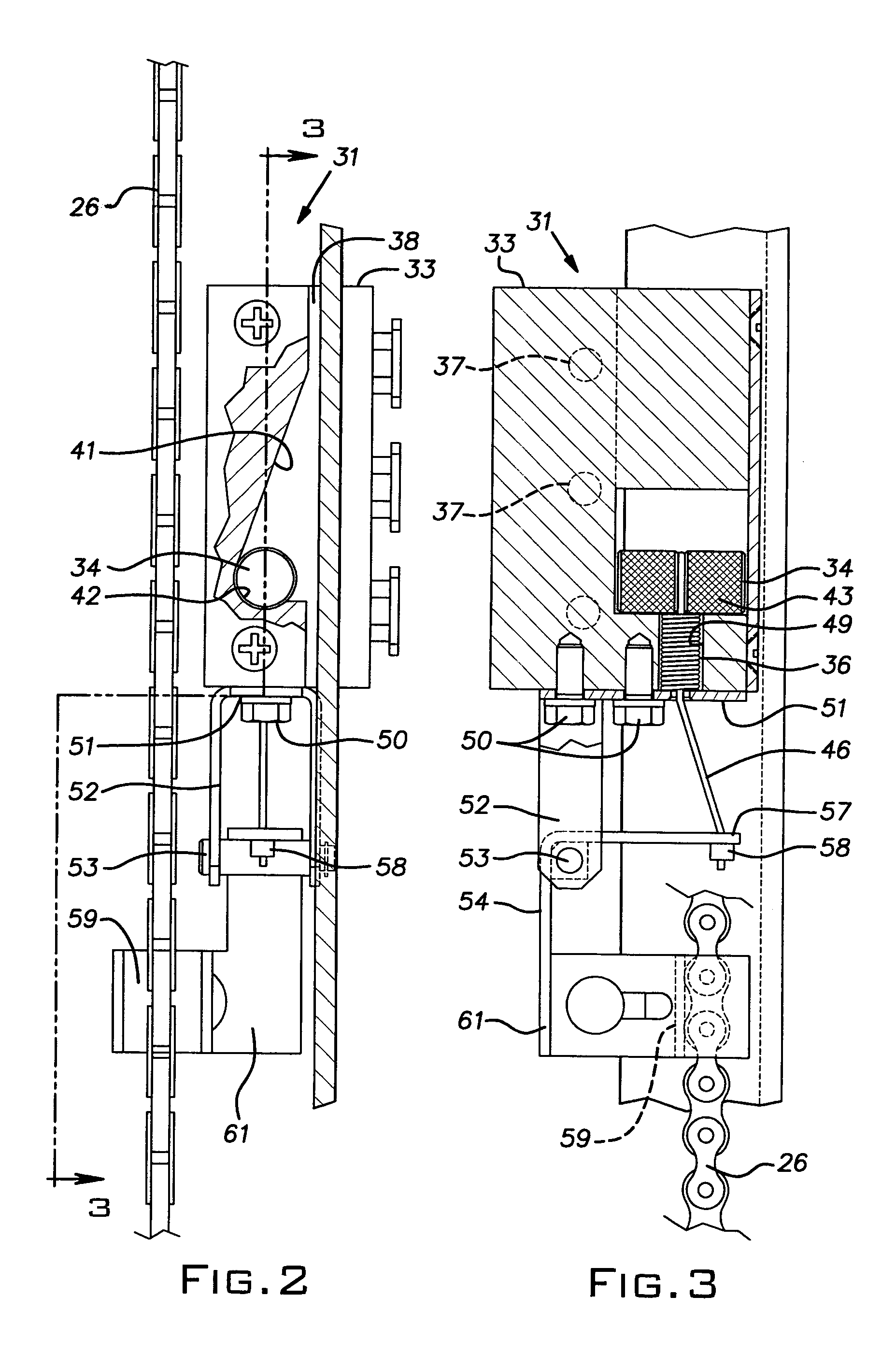
[0003]The invention provides a safety brake for vertically sliding freight elevator doors that is responsive to the failure of a suspension chain. The brake is readily adapted to conventional door panels and combinations of panels such as found in bi-parting door types, raise to open types, and lower to open types. The brake of the invention comprises a caliper housing or block fixed to the door panel and a roller cam in the caliper that work in conjunction with a door guide rail. The roller cam is released from an inactive position when a chain breaks, thereby enabling it to wedge lock the caliper to the guide rail. The caliper block and roller cam are preferably configured to enable to the roller cam to be retained in the inactive position, against a bias spring by a cable. The cable restraint feature enables the same basic brake caliper and roller cam components to be used on both upper and lower door panels with only limited variation in hardware to accommodate differences in the locations of a suspension chain relative to the associated door panel.

Problems solved by technology

The suspension chains and related components can fail through undetected wear and / or accidental damage, for example.
Where a chain breaks, the door panel has the potential to fall and cause personal injury and / or property damage to objects below the panel as well as to the panel itself.
The inertia of the block can slow its reaction time and any resistance on the surfaces constraining its movement can lead to a malfunction.
This patent does not disclose an arrangement that can be used with a lower panel of a bi-parting door unit.

Method used


Image

  • Elevator landing door broken chain safety device
  • Elevator landing door broken chain safety device
  • Elevator landing door broken chain safety device

Examples


Embodiment Construction

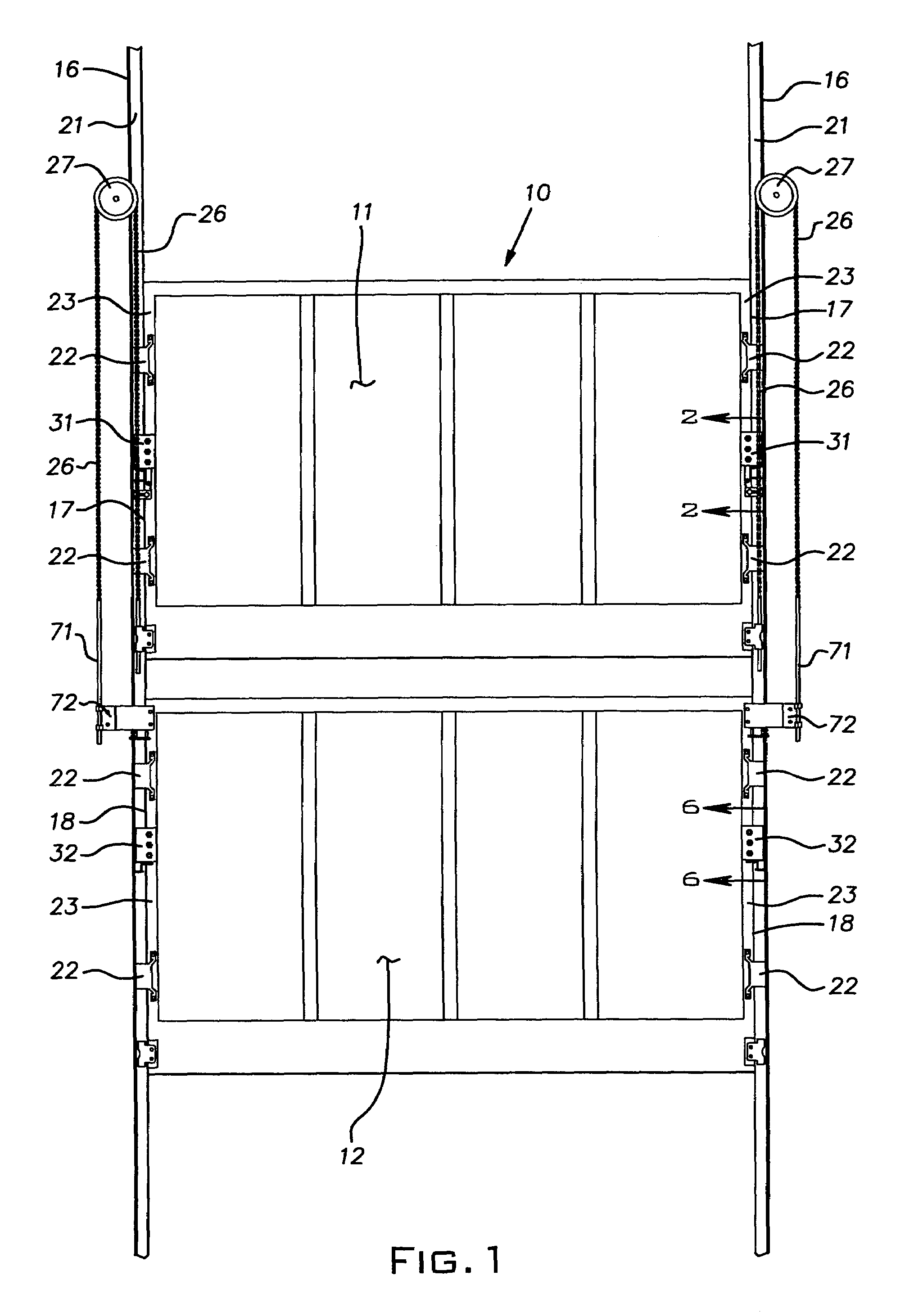
[0013]Referring now to the drawings and, in particular to FIG. 1, there is shown a freight elevator landing door 10 from the hoistway or shaft side of the door. The illustrated door 10 is a bi-parting type having upper and lower vertically sliding panels 11 and 12. In a conventional manner, the door panels 11, 12, move in opposite directions-toward one another to close and away from one another to open. Typically, the panels 11, 12 are fabricated of sheet steel and structural steel elements such as angles and channels. The panels 11, 12 are guided for vertical movement on parallel vertical guide rails 16, one adjacent each vertical edge 17, 18 of the panels 11, 12, respectively. The guide rails 16 are fixed to the building or other static structure by bolting, welding, or other appropriate technique. The guide rails have a U-shape or J-shaped shape cross-section; one of the flanges of each rail is fixed to the static structure as described and the opposite flange, designated 21 in t...


PUM


Abstract

A vertically sliding freight elevator landing door with a safety brake that deploys when a chain suspending the door breaks. The safety brake is adapted for use on both panels that slide up to open or that slide down to open. The brake, which is simple in construction and installation, comprises, principally, a caliber block fixed to the door and a roller cam assembled in the block. A spring biases the roller cam towards a wedge lock position while a cable normally holds the roller cam in an inactive position. The cable and, therefore, the roller cam are released when the associated door suspension chain breaks. The roller cam, operating between a tilted internal surface in the caliper block and a door guide rail quickly frictionally brakes the door on the guard rail.

Description

BACKGROUND OF THE INVENTION[0001]The invention relates to freight elevator landing doors and, in particular, to a device for stopping a vertically operating door in the event its suspension fails.PRIOR ART[0002]Freight elevator doors are typically arranged to slide vertically to open and close the opening to a hoistway and an elevator car. A common arrangement for such a door comprises a pair of bi-parting panels, an upper panel and a lower panel, that move vertically towards one another to close and vertically away from one another to open. Other vertically sliding door panel arrangements include slide up to open single or double panels, for example, and slide down to open panels. Ordinarily, each door panel is suspended by a chain, cable or other flexible strand-like element adjacent its vertical edges. The suspension chains and related components can fail through undetected wear and / or accidental damage, for example. Where a chain breaks, the door panel has the potential to fall ...

Claims


Application Information

Patent Timeline
Patent Type & Authority Patents(United States)
IPC IPC(8): B66B5/16B66B13/06B66B13/26E05D13/00
CPCB66B13/06E05D13/006E05Y2900/106E05Y2900/104
Inventor REYNOLDS, STEVEN P.LAJEUNESSE, RICHARD W.DZIWAK, ZYGMUNTKAIRIS, DAVID E.
Owner PEELLE COMPANY LTD THE
Learn More