
Laser blood-flow meter and system for monitoring bio-data

a technology of bio-data and blood flow meter, which is applied in the field of laser blood flow meter and system for monitoring bio-data, can solve the problems of difficult or almost impossible difficult or fast to properly measure blood flow, and often extremely high noise, so as to achieve the effect of ensuring and stably measuring blood flow

Inactive Publication Date: 2006-08-22
CYBERFIRM
View PDF22 Cites 12 Cited by
  • Summary
  • Abstract
  • Description
  • Claims
  • Application Information

AI Technical Summary

Benefits of technology

[0018]In view of the above-mentioned problem, it is an object of the present invention to provide a laser blood-flow meter and a system for monitoring bio-data both of which are capable of being less influenced by artifact noises, and readily and stably measuring blood flow in a head and quarters independently of each other.
[0021]Since the laser blood-flow meter in accordance with the present invention includes the beam-collector, it would be possible to collect scattered beams, and amplify signals necessary for measurement of blood flow. That is, it would be possible to reduce artifact noises relatively to the signals, and hence, the laser blood-flow meter could be less influenced by artifact noises. Thus, it is now possible to solve the problem that blood flow cannot be properly measured because of artifact noises. Hence, it is also possible to apply the laser blood-flow meter in accordance with the present invention to a monitor system which is necessary to receive for a long time blood flow data and biological data having correlation with the blood flow. Furthermore, the laser blood-flow meter in accordance with the present invention can readily and stably measure blood flow in a head and quarters independently of each other
[0023]The laser blood-flow meter may further include a case (110a) in which the laser-beam irradiator (12), the beam-collector (15) and the detector (13) are arranged, in which case, it is preferable that the case (110a) has a flat contact-surface (101), as at least a part of an external surface thereof, at which the case (110a) makes contact with a surface of the biological structure (11) when blood flow of the biological structure (11) is measured, and the laser-beam irradiator (12), the beam-collector (15) and the detector (13) are arranged in this order on a path substantially parallel with the flat contact-surface (101). Thus, it is possible to render the contact-surface more stable, ensuring that the laser blood-flow meter is less influenced by artifact noises during measurement of blood flow.
[0039]In accordance with the above-mentioned system, blood flow and a blood-flow waveform obtained when the blood flow and the blood-flow waveform of the head is not in synchronization with the blood flow and the blood-flow waveform of the any one of quarters are not used for monitoring bio-data, ensuring that bio-data is monitored based on blood flow and a blood-flow waveform both having been properly measured. That is, blood flow and a blood-flow waveform both much influenced by artifact noises are not used for monitoring bio-data, and accordingly, it is ensured that the laser blood-flow meter is less influenced by artifact noises. Furthermore, when blood flow and a blood-flow waveform of a head and quarters are measured independently of each other, it would be possible to readily and stably do so.
[0048]In accordance with the present invention, it is possible to reduce harmful influence caused by artifact noises, and readily and stably measure blood flow of a head and quarters independently of each other continuously for a long time.

Problems solved by technology

The artifact noises often become extremely high in proportion with power spectrum of scattered beams, in which case, it is not possible to properly measure blood flow.
Thus, it was difficult or almost impossible to properly measure blood flow by applying a laser blood-flow meter to a monitor system which was necessary to receive for a long time blood flow data and biological data having correlation with the blood flow.
Hence, it has been said that blood flow in a head and quarters were necessary to be measured independently of each other, but it was not possible to do so because of the above-mentioned artifact noises.

Method used


Image

  • Laser blood-flow meter and system for monitoring bio-data
  • Laser blood-flow meter and system for monitoring bio-data
  • Laser blood-flow meter and system for monitoring bio-data

Examples


first embodiment

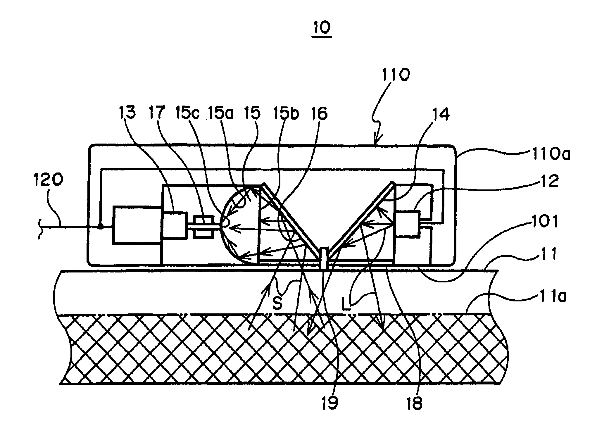
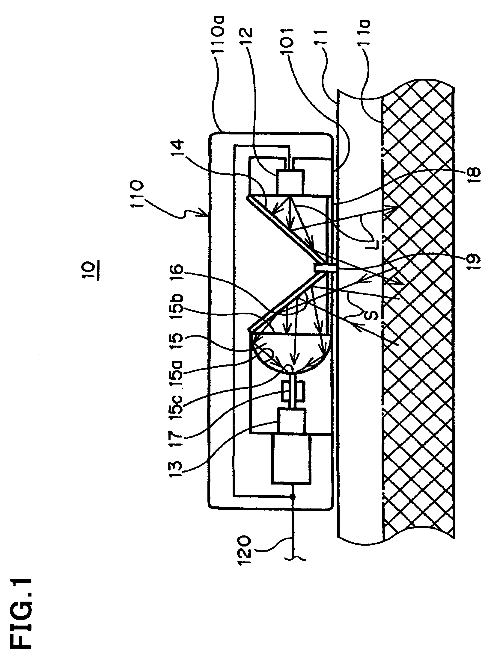
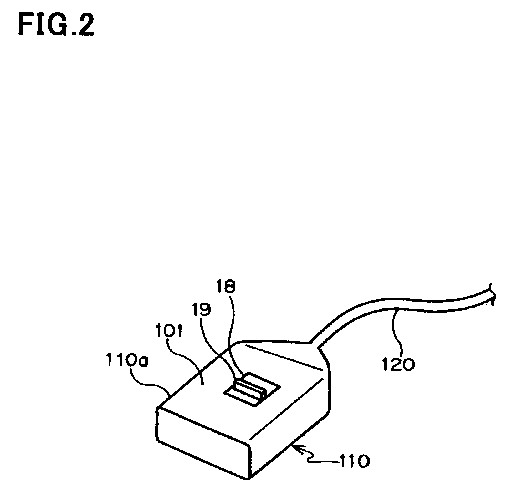
[0060]The laser blood-flow meter in accordance with the first embodiment is of a backward-scattered type. Hereinbelow is explained the laser blood-flow meter in accordance with the first embodiment with reference to FIGS. 1 and 2, wherein FIG. 1 is a cross-sectional view of the laser blood-flow meter, and FIG. 2 is a perspective view of the laser blood-flow meter. A later-mentioned contact surface 101 faces downwardly in FIG. 1, whereas the same faces upwardly in FIG. 2.

[0061]As illustrated in FIG. 1, the laser blood-flow meter 10 in accordance with the first embodiment is comprised of a laser-beam irradiator 12 for irradiating laser beams L to biological structure 11, a detector 13 for detecting scattered beams S resulted from scattering of the laser beams L in the biological structure 11, and an operation unit (not illustrated) which measures or calculates blood flow of the biological structure 11 in accordance with power spectrum of the scattered beams S detected by the detector ...

second embodiment

[0124]FIGS. 5 and 6 illustrate a laser blood-flow meter 20 in accordance with the second embodiment.

[0125]Since the laser blood-flow meter 20 is structurally identical with the laser blood-flow meter 10 except a later-mentioned difference, parts or elements that correspond to the laser blood-flow meter 10 have been provided with the same reference numerals, and are not explained.

[0126]As illustrated in FIG. 5, the detector 13 and the laser-beam irradiator 12 in the laser blood-flow meter 20 are disposed on opposite sides to each other relative to the biological structure 11 such that the detector 13 detects forward-scattered beams S. That is, the laser blood-flow meter 20 in accordance with the second embodiment is of a forward-scattered type meter.

[0127]Unlike the laser blood-flow meter 10 in accordance with the first embodiment, the laser blood-flow meter 20 is not necessary to include the first and second light-reflectors 14 and 16, and the beam-block 19.

[0128]The laser blood-flo...

third embodiment

[0145]The third embodiment relates to a system for monitoring bio-data.

[0146]As illustrated in FIG. 7, a bio-data monitoring system 30 in accordance with the third embodiment of the present invention includes the laser blood-flow meter 20 for measuring blood flow of a head 31a (for instance, an ear lobe) of a man 31, and the laser blood-flow meter 10 for measuring blood flow in any one of quarters of the man 31, for instance, a leg 31b. The system 30 monitors bio-data of the man 31, based on the measured blood flow in the head 31a and the leg 31b.

[0147]The laser blood-flow meters 10 and 20 are controlled commonly by a controller 40.

[0148]The controller 40 is comprised of an input section 41 which receives detection signals transmitted from the sensor units 110 of the laser blood-flow meters 10 and 20, and converts the received analog detection signals into digital signals, a calculator 42 which calculates blood flow of the man 31, based on the digital detection signals, and an outp...


PUM


Abstract

A laser blood-flow meter includes a laser-beam irradiator for irradiating laser beams to biological structure, a detector for detecting scattered beams resulted from scattering of the laser beams in the biological structure, the laser blood-flow meter measuring blood flow of the biological structure in accordance with the scattered beams detected by the detector, and a beam-collector for collecting the scattered beams to direct the collected beams to the detector.

Description

BACKGROUND OF THE INVENTION[0001]1. Field of the Invention[0002]The invention relates to a laser blood-flow meter and a system for monitoring bio-data.[0003]2. Description of the Related Art[0004]Japanese Patent Application Publication No. 2002-45342 has suggested a laser blood-flow meter which irradiates laser beams to biological structure to allow the laser beams to be scattered in the biological structure, and detect power spectrum of scattered laser beams to thereby measure blood flow in the biological structure.[0005]The suggested laser blood-flow meter measures or calculates blood flow by virtue of a speckle interference process making use of diffraction of laser beams scattered in biological structure.[0006]Herein, speckle interference indicates, with respect to measurement of blood flow, a spotted noise or interference pattern obtained when scattered beam resulted when laser beams irradiated to biological structure are scattered with erythrocytes in blood are observed at a f...

Claims


Application Information

Patent Timeline
Patent Type & Authority Patents(United States)
IPC IPC(8): A61B6/00A61B5/00A61B5/026A61M1/14G01F1/00G01P5/00H01L31/12
CPCA61B5/0261
Inventor MIYAHARA, TAKAAKIMISHIMA, KAZUTONIWAYAMA, JUNYANAGI, TOMIKO
Owner CYBERFIRM
Learn More