
Direct-conversion receiver for a communication system using a modulation with non-constant envelope

a direct conversion and receiver technology, applied in the field of cdma systems, can solve problems such as information loss, dc voltage offset and second-order distortion, and architecture unfortunately exhibits some drawbacks, and achieve the effect of improving the evaluation of dc offset voltag

Active Publication Date: 2006-08-22
MICROELECTRONIC INNOVATIONS LLC
View PDF9 Cites 4 Cited by
  • Summary
  • Abstract
  • Description
  • Claims
  • Application Information

AI Technical Summary

Benefits of technology

[0014]Another object of the present invention is to reduce the number of external components of the direct-conversion receiver to obtain a high level of integration that is structurally independent of the digital stage of the receiver. The receiver is preferably compatible with the majority of existing terminals.
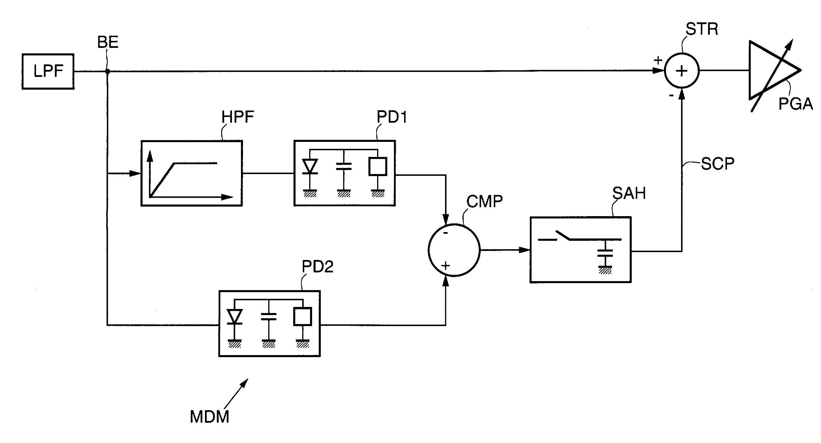
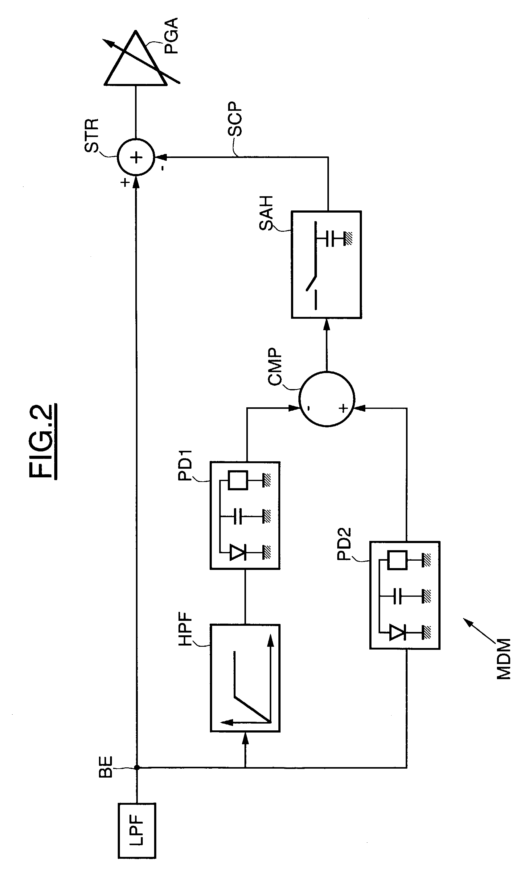
[0019]The analog stage may further comprise low-pass filtering means downstream of the transposition means. The input terminal of the compensation module is then preferably downstream of the low-pass filtering means, thereby making it possible to eliminate the high-frequency spurious sources and to improve the evaluation of the DC offset voltage.

Problems solved by technology

Such an architecture unfortunately exhibits some drawbacks, such as a DC voltage offset and second-order distortion.
The static offset is due to matching errors in the method of manufacturing the receiver, while the dynamic offset stems mainly from the non-linear characteristics and from leakages between the inputs of the mixers of the receiver.
This causes a loss of information, thereby appreciably increasing the bit error rate (BER).
All the approaches to this problem which have been developed for constant-envelope modulations, such as in GSM systems for example, are not suitable for systems using modulation with a non-constant envelope, such as in CDMA-FDD systems for example.

Method used


Image

  • Direct-conversion receiver for a communication system using a modulation with non-constant envelope
  • Direct-conversion receiver for a communication system using a modulation with non-constant envelope
  • Direct-conversion receiver for a communication system using a modulation with non-constant envelope

Examples


Embodiment Construction

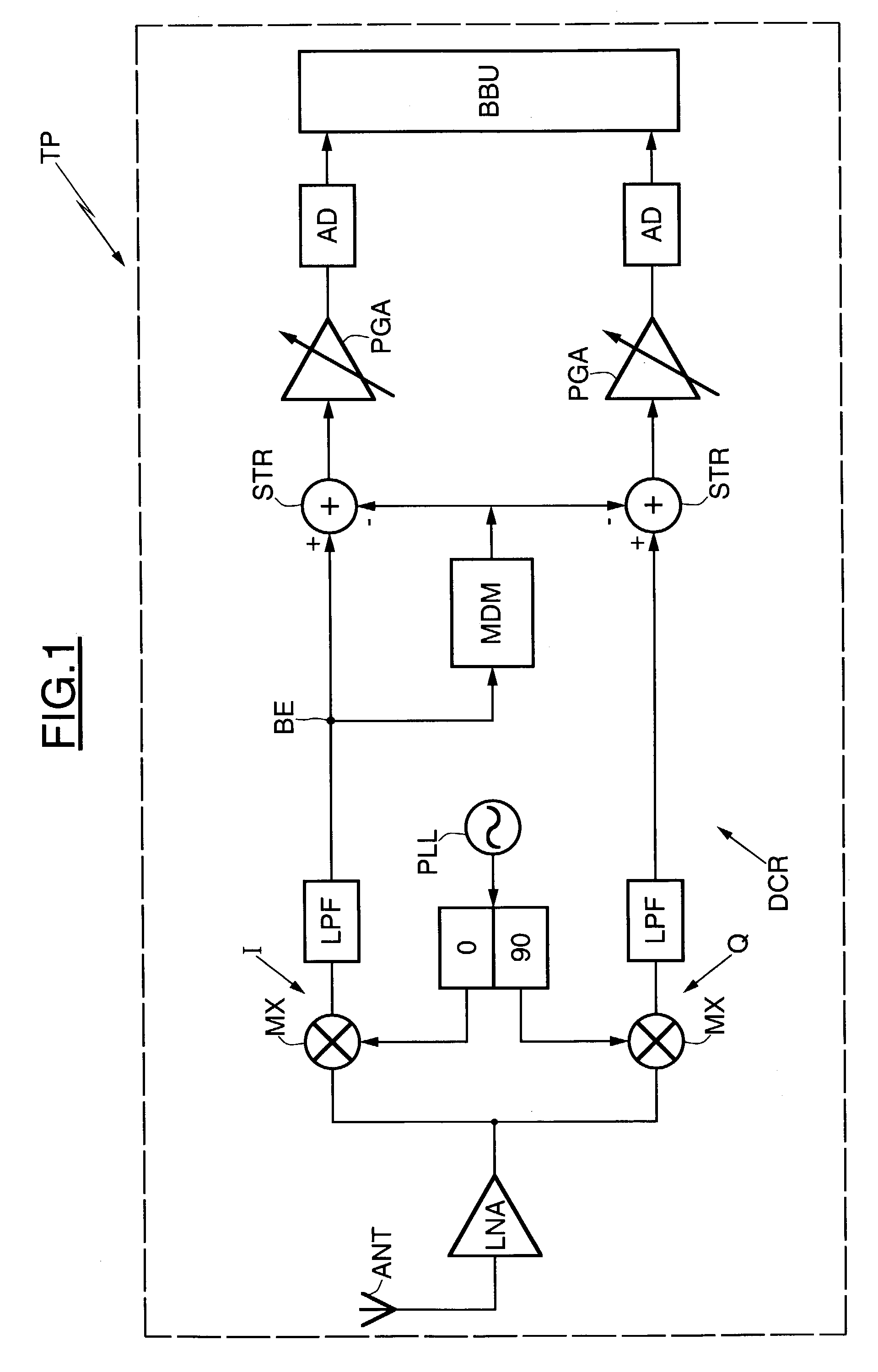
[0029]In FIG. 1, the reference TP designates a remote terminal such as a cellular mobile telephone which is in communication with a base station. The cellular telephone TP comprises a direct-conversion receiver DCR connected to an antenna ANT for receiving an incident signal emanating from a transmission channel.

[0030]The direct-conversion receiver DCR comprises an analog stage connected to a digital stage. The digital stage is also referred to as a baseband processing unit BBU, and is connected across a pair of illustrated analog digital conversion stages AD. Conventionally, the analog stage comprises a low noise amplifier LNA and two processing pathways respectively including a mixer MX (transposition means), a conventional low-pass filter LPF and a programmable-gain amplifier PGA.

[0031]The two mixers MX respectively receive from a phase-locked loop PLL two signals mutually exhibiting a phase difference of 90 degrees. After frequency transposition in the mixers, the two processing...


PUM


Abstract

A direct-conversion receiver includes an analog stage for receiving an incident signal from a transmission channel, mixers and programmable-gain amplifiers. The receiver further includes at least one compensation module having input and output terminals respectively connected between the output of the mixers and the input of the programmable-gain amplifiers. The compensation module compensates for both a static DC voltage offset and a possible dynamic DC voltage offset of the analog stage.

Description

FIELD OF THE INVENTION[0001]The present invention relates in general to wireless communication systems, and in particular, to CDMA systems.BACKGROUND OF THE INVENTION[0002]In a wireless communication system, a base station communicates with a plurality of remote terminals, such as cellular mobile telephones. Frequency division multiple access (FDMA) and time division multiple access (TDMA) are the traditional multiple access schemes for delivering simultaneous services to a number of terminals. The basic idea underlying FDMA and TDMA systems is based upon sharing the available resource, respectively as several frequencies or as several time intervals, so that several terminals can operate simultaneously without causing interference.[0003]Telephones operating according to the GSM standard belong to the FDMA and TDMA systems in the sense that transmission and reception are performed at different frequencies and also at different time intervals. Moreover, a GSM signal is a phase-modula...

Claims


Application Information

Patent Timeline
IPC IPC(8): H04B1/10H04B1/707H04B1/30H04J13/00H04L25/06H04L27/22
CPCH04B1/30H04L27/22H04L25/062
Inventor CONTI, PATRICK
Owner MICROELECTRONIC INNOVATIONS LLC
Learn More