Method and apparatus for separation of particles in a microfluidic device
a microfluidic device and particle technology, applied in the field of microfluidic devices, can solve the problems of incompatibility of reagent components with each other, difficult preparation of such devices, and inability to achieve desired reaction
- Summary
- Abstract
- Description
- Claims
- Application Information
AI Technical Summary
Benefits of technology
Problems solved by technology
Method used
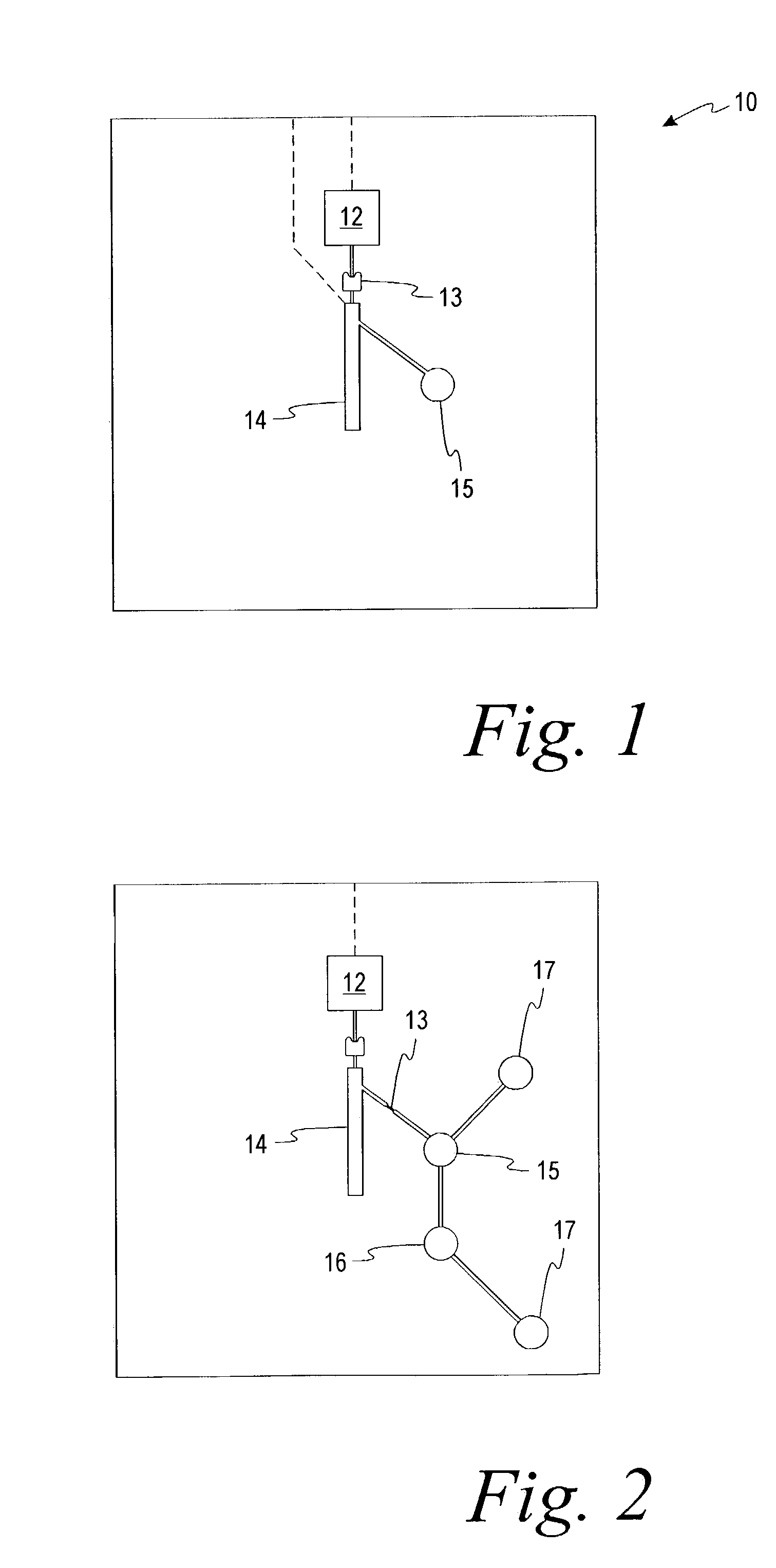
Image


Examples
example 1
Separation of Blood
[0047]A 5 μL blood sample treated with EDTA was added to a sample well in a microfluidic chip having wall surfaces with a contact angle relative to water of 30°. The chip was spun at 600 to 2500 rpm for 2 minutes, with the center of the sample well 1.5 cm from the center of rotation to transfer the sample to a separation chamber 6 mm long, 1 mm wide and 0.5 mm deep, except for a 1 mm depth at the lower 1.5 mm of the chamber.
[0048]All outlet capillaries connected to the separation chamber were blocked with plasticine to keep all the blood in the separation chamber for a determination of blood separation effectiveness. The blood sample was added to the inlet port. The chip was spun and the chip image was saved every 30 seconds. The experiment was repeated several times at different spinning speeds. The degree of separation was determined by comparison of the observed to the actual hematocrit value. The observed hematocrit value measured optically by a ratio of the s...
example 2
Quick Separation of a Plasma Aliquot
[0050]A 5 μL blood sample treated with EDTA was added to a sample well in a microfluidic chip having wall surfaces with a contact angle relative to water of 30°. The chip was spun at 1000 rpm for 30 seconds, with the center of the sample well 1.5 cm from the center of rotation to transfer the sample to a separation chamber 6 mm long, 1 mm wide and 0.5 mm deep, except for a 1 mm depth at the lower 1.5 mm of the chamber.
[0051]An outlet capillary was connected to the separation chamber. The dimensions of this outlet chamber were varied from a depth of 10 μm to a depth of 200 μm with a width of 100 μm. The blood sample was added to the inlet port. The chip was spun and the chip image was saved every 30 seconds. The experiment was repeated several times at different spinning speeds.
[0052]Results showed the quickly separated plasma sample flowed from the separation chamber easily into the outlet capillary and subsequent holding areas at 30 seconds and 1...
example 3
Hematocrit Measurement with Blood Separation Chip
[0053]A 5 μL blood sample treated with EDTA was added to a sample well in a microfluidic chip having a wall surface with a contact angle relative to water of 30°. The chip was spun at 2500 rpm for 120 seconds, with the center of the sample well 1.5 cm from the center of rotation to transfer the sample to a separation chamber 6 mm long, 1 mm wide and 0.5 mm deep, except for a 1 mm depth at the lower 1.5 mm of the chamber.
[0054]All outlet capillaries connected to the separation chamber were blocked with plasticine to keep all the blood in the separation chamber for determining the hematocrit measurement effectiveness.
[0055]The hematocrit study was done with different blood samples to assess the utility of the blood separation chip in hematocrit determination within the normal physiological range (30˜60%). Five microliters of each blood sample were transferred to the separation chip and spun at 2500 rpm for 2 minutes. The last chip image...
PUM
| Property | Measurement | Unit |
|---|---|---|
| Time | aaaaa | aaaaa |
| Angle | aaaaa | aaaaa |
| Angle | aaaaa | aaaaa |
Abstract
Description
Claims
Application Information
 - R&D
- Intellectual Property
- Life Sciences
- Materials
- Tech Scout
- Unparalleled Data Quality
- Higher Quality Content
- 60% Fewer Hallucinations
Browse by: Latest US Patents, China's latest patents, Technical Efficacy Thesaurus, Application Domain, Technology Topic, Popular Technical Reports.
© 2025 PatSnap. All rights reserved.Legal|Privacy policy|Modern Slavery Act Transparency Statement|Sitemap|About US| Contact US: help@patsnap.com