Eureka AIR delivers breakthrough ideas for toughest innovation challenges, trusted by R&D personnel around the world.

Filter device

a filter device and filter technology, applied in the direction of moving filter element filters, filtration separation, separation processes, etc., can solve the problems of shortening the lifetime of the filter, affecting the filter, and affecting the filter performance, so as to prevent any agitation of the deposi

Inactive Publication Date: 2006-08-22
NOK CORP
View PDF14 Cites 11 Cited by
  • Summary
  • Abstract
  • Description
  • Claims
  • Application Information

AI Technical Summary

Benefits of technology

[0017]An object of the present invention is to prevent the deterioration of filtration performance caused by impurities which are filtered and separated.
[0020]Consequently, the impurity particles which are not filtered but separated can be deposited and recovered in the deposit recovery tank, thereby reducing the adhesion and deposition of the impurity particles to and in a membrane of the filter.
[0022]As a consequence, it is possible to prevent any agitation of the deposit deposited inside of the deposit recovery tank by the flowing liquid to be filtered.
[0026]As a consequence, it is possible to prevent any agitation of the floating material recovered in the floating material recovery tank by the flowing liquid to be filtered.
[0028]Consequently, the impurity particles which are not filtered but separated in the deposit recovery tank can be deposited and recovered, thereby reducing the adhesion and deposition of the impurity particles to and in a membrane of the filter, and the filtration and separation by the filter and the specific gravity difference separation based on a specific gravity difference can be performed by a single device.
[0030]As a consequence, it is possible to prevent any agitation of the deposit deposited inside of the deposit recovery tank by the flowing liquid to be filtered and the floating material recovered in the floating material recovery tank by the flowing liquid to be filtered.

Problems solved by technology

Therefore, the impurities to be filtered are liable to stay at the lower portion of the bag-like filter.
This shortens the lifetime of the filter.
As a consequence, the bag filter 100 cannot perform the specific gravity difference separation.

Method used


Image

  • Filter device
  • Filter device
  • Filter device

Examples


first embodiment

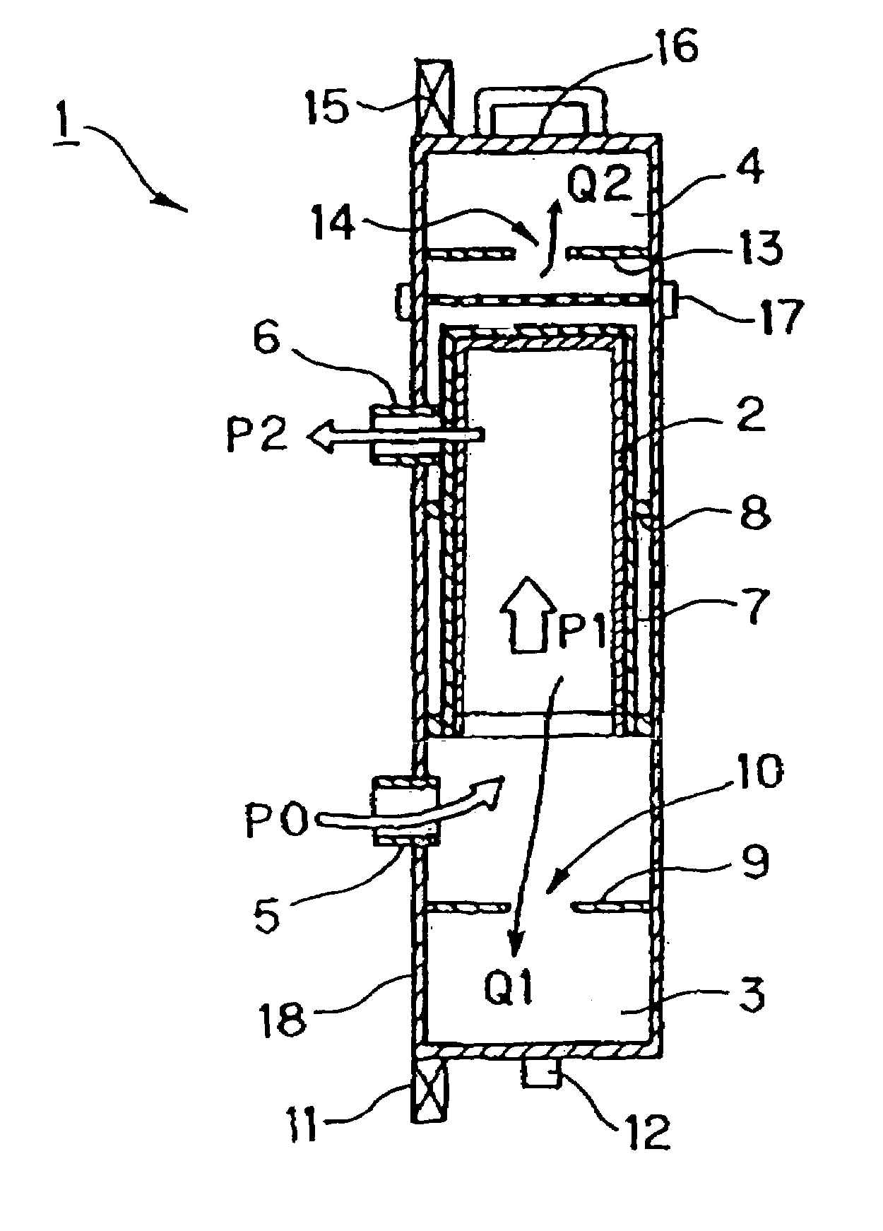
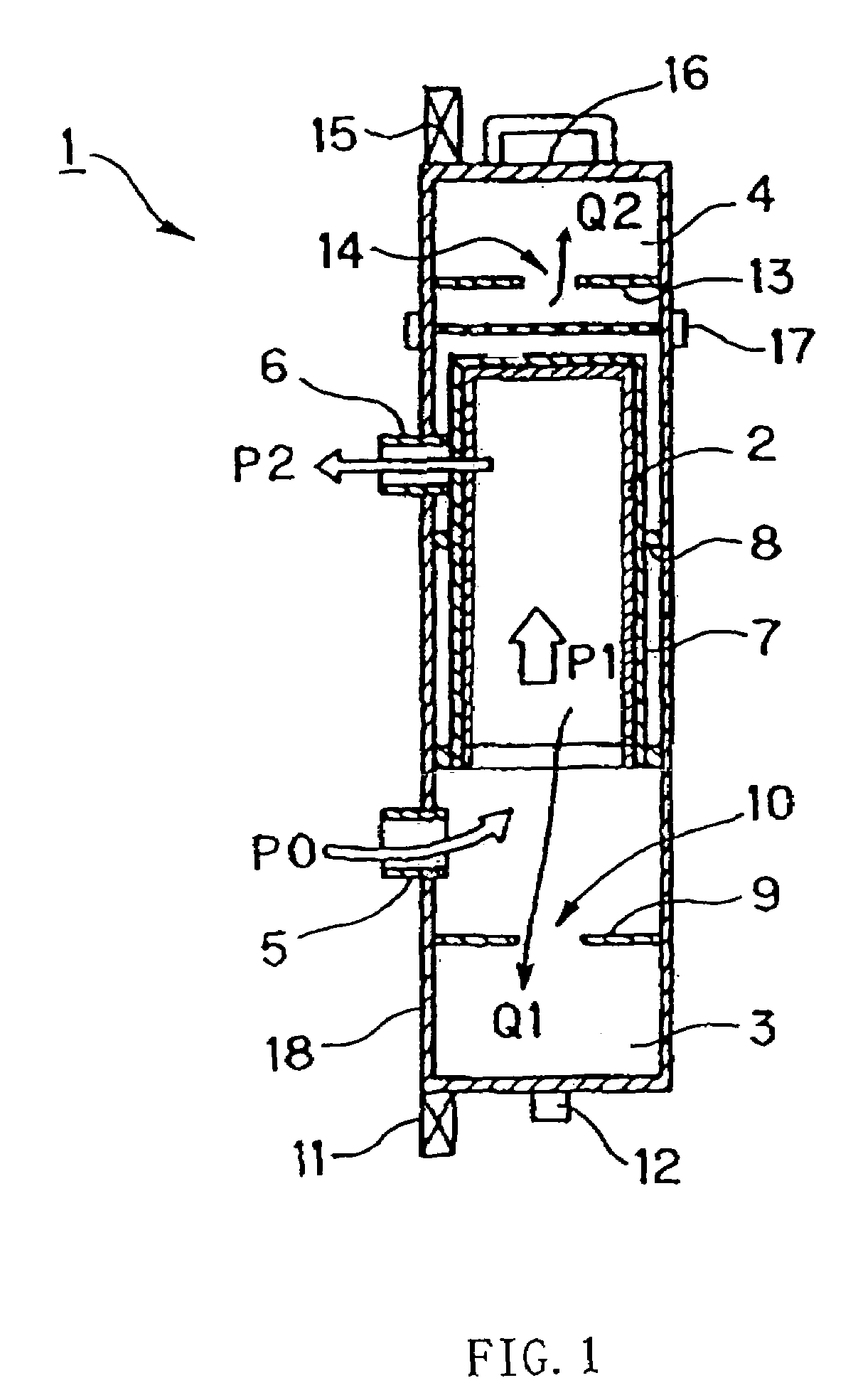
[0052]Referring to FIG. 1, explanation will be made on a filter device according to a first embodiment of the present invention. FIG. 1 is a cross-sectional view schematically showing the configuration of the filter device according to the first embodiment of the present invention.

[0053]As shown in FIG. 1, a filter housing 18 in a filter device 1 in the present embodiment comprises a container for accommodating a filter bag (a bag-like filter) 2, a deposit recovery tank 3 for recovering a deposit and a floating material recovery tank 4 for recovering a floating material.

[0054]The filter bag 2 is covered with a mesh-like bag filter bucket 7 made of metal or the like, and thus, is protected. Furthermore, the filter bag 2 is positioned by a filter presser 8 disposed at the filter housing 18. Moreover, the filter device 1 in the present embodiment is used in the state in which the opening of the bag-like filter bag 2 is oriented downward.

[0055]The deposit recovery tank 3 is located at a...

example 1

[0074]FIG. 3 is a diagram illustrating the flow in a filter system to recycle the cleaning liquid.

[0075]In this filter system, a pump 40 is disposed downstream of a cleaning tank 30 containing the cleaning liquid therein, and further, a filter device 1 is disposed downstream of the pump 40.

[0076]The cleaning liquid contained inside of the cleaning tank 30 flows in a direction indicated by an arrow A by means of the pump 40. And then, the cleaning liquid flows in a direction indicated by an arrow B, and thus, flows into the filter device 1. As described above, by the filter device, the cleaning liquid is subjected to impurity separation by the filtration of the filter and separation of a component small in specific gravity by the specific gravity difference separation. Thereafter, cleaning liquid flows in a direction indicated by an arrow D, and thus, is returned to the cleaning tank 30.

[0077]Incidentally, recovered deposit is appropriately discharged in a direction indicated by an a...

example 2

[0078]FIG. 4 is a diagram illustrating the flow in a filter system to recycle the cleaning liquid.

[0079]In the filter system in this example, a hollow fiber membrane module (UF: ultrafiltration) 50 is disposed downstream of a filter device 1, unlike the system in Example 1. In this system, liquid filtered by the filter device 1 is further cross-flow filtered by the hollow fiber membrane module 50. Consequently, finer impurities can be removed. The cross-flow filtration by the hollow fiber membrane module 50 can suppress adhesion of particles and oil to a hollow-fiber membrane, thereby achieving a stable transmitted liquid flow rate. Liquid which cannot be filtered by the hollow fiber membrane module 50 is returned to the upstream side of a pump 40.

[0080]Incidentally, in this system, a condensed deposit and floating material are continuously recovered and discharged. Consequently, the cleaning liquid is allowed to steadily flow on a circulation path.


PUM

PropertyMeasurementUnit
specific gravityaaaaaaaaaa
flow rateaaaaaaaaaa

Abstract

The present invention relates to a filter device for removing impurities contained in liquid. A filter housing 18 is provided with a container for accommodating a filter bag 2 therein, a deposit recovery tank 3 for recovering a deposit and a floating material recovery tank 4 for recovering a floating material. Thus, it is possible to prevent any deterioration of filtration performance caused by filtered and separated impurities, and to achieve both of filtration and specific gravity difference separation by a single device.

Description

BACKGROUND OF THE INVENTION[0001]1. Field of the Invention[0002]The present invention relates to a filter device for removing impurities contained in liquid, and so on.[0003]2. Description of the Related Art[0004]There has been conventionally used a filter device by the use of a bag filter for the purpose of cleaning of liquid or the disposal of waste liquid.[0005]A filter device in the conventional art will be explained in reference to FIGS. 18 to 20. FIG. 18 is a cross-sectional view schematically showing the configuration of a bag filter in the conventional art; and FIGS. 19 and 20 are diagrams illustrating the flow of a filter system by the use of the bag filter in the conventional art.[0006]A bag filter 100 in the conventional art comprises a filter bag (bag-like filter) 101, a mesh-like bag filter bucket 102 for protecting the filter bag 101 and a filter presser 105 for positioning the filter bag 101. These are housed inside of a filter housing 108 (see FIG. 18).[0007]Furtherm...

Claims


Application Information

Patent Timeline
Patent Type & Authority Patents(United States)
IPC IPC(8): B01D29/27B01D17/02B01D36/04C02F1/40B01D29/11B01D29/23B01D36/00
CPCB01D17/0214B01D29/23B01D36/003B01D17/045B01D17/085B01D36/04B01D2201/34B01D2201/403
Inventor SHIRAKAWA, HIROYASUARAMAKI, TOSHIHIROTOMINAGA, ICHIRO
Owner NOK CORP
Why Eureka
Eureka Blog
Learn More