
Magnetic tape drive with recording head group providing high density data signal recording

Active Publication Date: 2006-08-15
FUJIFILM CORP +1
View PDF8 Cites 8 Cited by
  • Summary
  • Abstract
  • Description
  • Claims
  • Application Information

AI Technical Summary

Benefits of technology

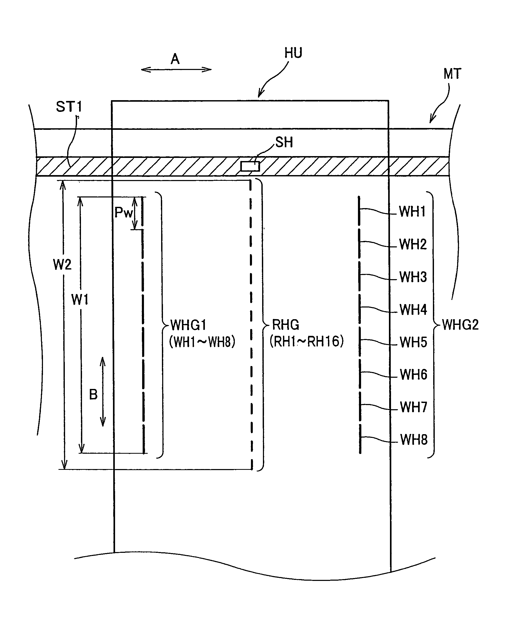
[0018]Thus setting the head width of the data signal reproducing heads not less than Pw×0.2, they can sufficiently obtain a needed output, thereby data tracks being able to be surely reproduced.

Problems solved by technology

Therefore, different from the conventional magnetic tape drive, it becomes unnecessary to provide a margin matching with a control amount error between the adjacent data tracks on the magnetic tape in moving the head unit in a lateral direction of the magnetic tape.

Method used


Image

  • Magnetic tape drive with recording head group providing high density data signal recording
  • Magnetic tape drive with recording head group providing high density data signal recording
  • Magnetic tape drive with recording head group providing high density data signal recording

Examples


Embodiment Construction

[0028]Here will be described one embodiment of a magnetic tape drive related to the present invention in detail, referring to drawings as needed.

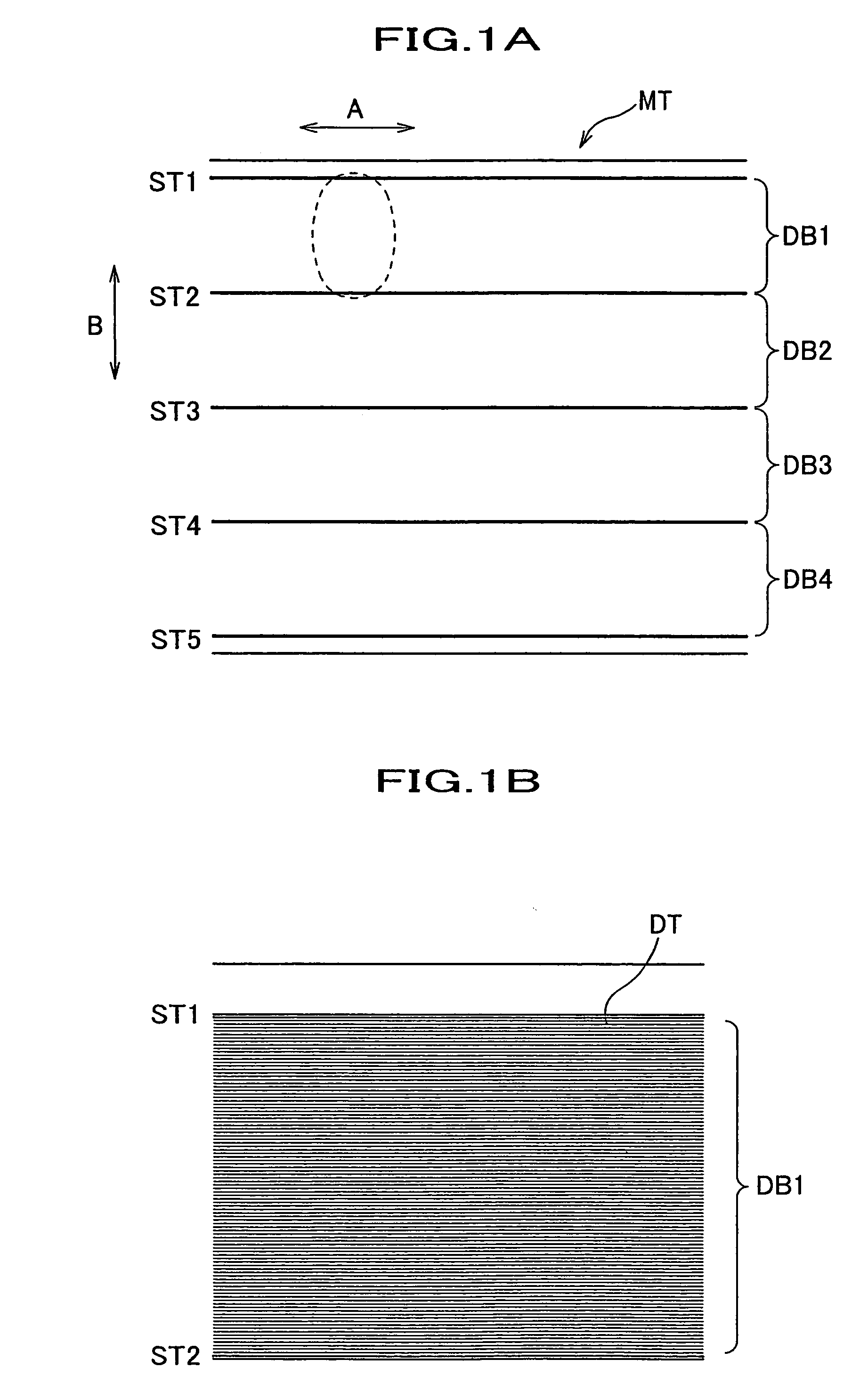
[0029]First, a magnetic tape reproduced by the magnetic tape drive of the present invention will be described, referring to FIGS. 1A and 1B.

[0030]A magnetic tape MT shown in FIG. 1A is a magnetic tape for a data backup having a width of a half inch, for example, according to the LTO (Linear Tape Open) standard. In longitudinal directions (travel directions) A of the magnetic tape MT five pieces of servo tracks ST1 to ST5 are written. Each of the servo tracks ST1 to ST5 is formed at an equal distance in lateral directions B of the magnetic tape MT. Meanwhile, the servo tracks ST1 to ST5 are written by a servo writer not shown.

[0031]And a region between each two adjacent tracks of the servo tracks ST1 to ST5 becomes a band (data band) where data signals are recorded by a magnetic tape drive 10. Since on the magnetic tape MT shown in FIG. 1A t...


PUM

PropertyMeasurementUnit
widthaaaaaaaaaa
distance Dwaaaaaaaaaa
distanceaaaaaaaaaa

Abstract

A magnetic tape drive of the present invention is the drive that has a head unit comprising a servo head for trackings and a recording head group, which comprises a plurality of data signal recording heads, wherein the plurality of the data signal recording heads are formed at a pitch corresponding to that of adjacent data tracks on a magnetic tape, and wherein a plurality of adjacent data tracks are simultaneously formed on the magnetic tape with the plurality of the data signal recording heads.

Description

BACKGROUND OF THE INVENTION[0001]1. Field of the Invention[0002]The present invention relates to a magnetic tape drive, and in particular, to the magnetic tape drive that can form data tracks in a lateral direction in a higher density, compared to a conventional magnetic tape drive.[0003]2. Description of the Related Art[0004]These years in a magnetic tape used for a data backup of a computer and the like, an augmentation of a memory capacity progresses and some magnetic tapes have a capacity of not less than 100 GB (gigabyte). When in such the magnetic tapes data tracks are formed along longitudinal directions (travel directions) thereof, a width of each data track itself and a distance between each data track are narrowed and a number of data tracks are increased, thereby a high density of the data tracks being intended.[0005]In order to record / reproduce data signals on such the magnetic tapes, a conventional magnetic tape drive is equipped with a head unit having a plurality of d...

Claims


Application Information

Patent Timeline
Patent Type & Authority Patents(United States)
IPC IPC(8): G11B5/584
CPCG11B5/584
Inventor KITAHARA, TOSHIYUKI
Owner FUJIFILM CORP
Learn More