Eureka AIR delivers breakthrough ideas for toughest innovation challenges, trusted by R&D personnel around the world.

System and method for testing an embedded microprocessor system containing physical and/or simulated hardware

a microprocessor and embedded system technology, applied in the field of embedded system testing, can solve the problems of inability to test a complete target program, inability to use the target software and hardware to test, and extremely slow and cumbersome hardware simulators

Inactive Publication Date: 2006-08-08
NXP USA INC
View PDF1 Cites 14 Cited by
  • Summary
  • Abstract
  • Description
  • Claims
  • Application Information

AI Technical Summary

Benefits of technology

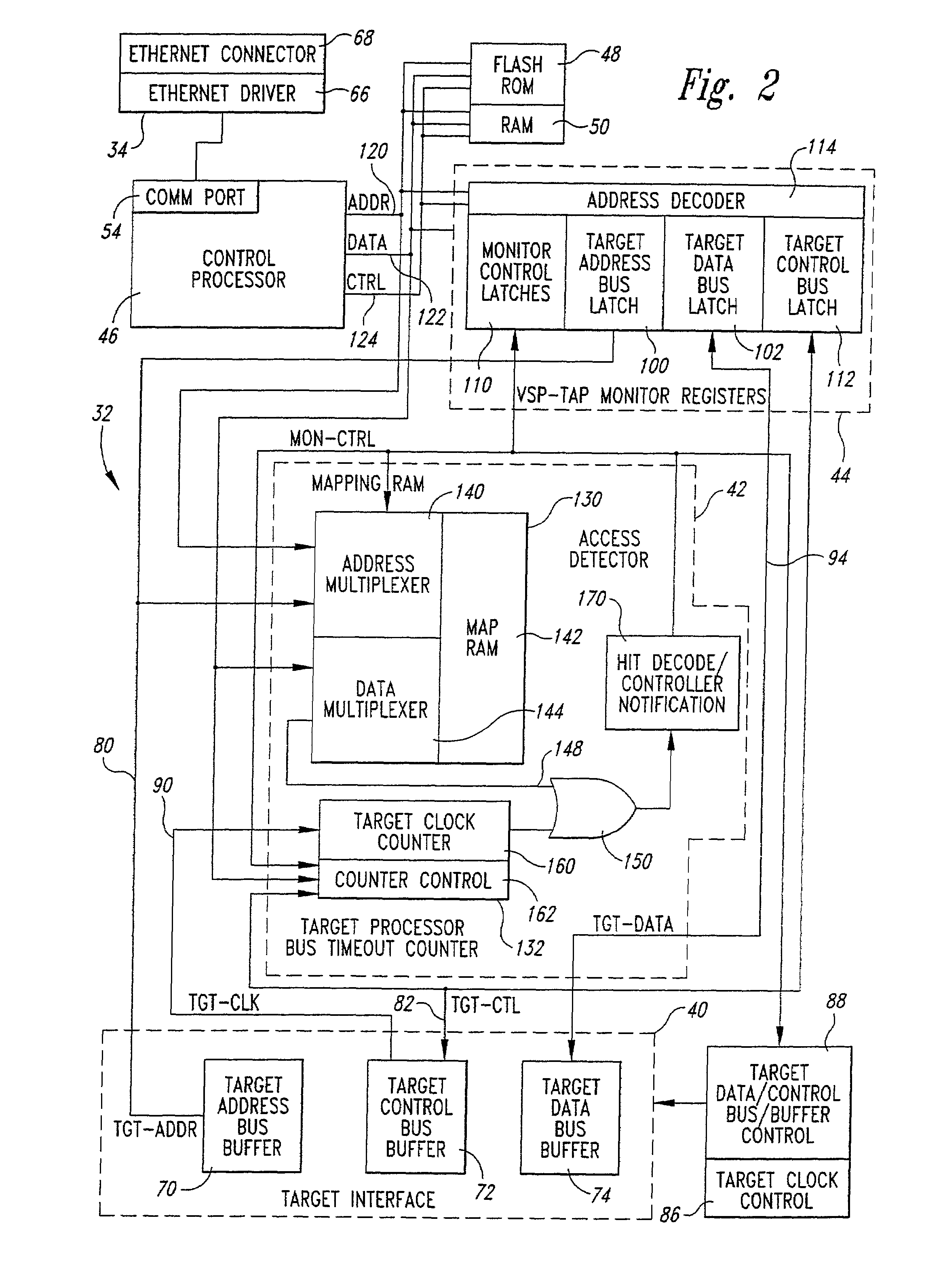
[0013]The target monitor preferably detects an access to the simulated physical hardware in either of two modes. In the first mode, the target monitor detects that the target processor has issued an address that is in the address space of the simulated target hardware. In the second mode, the target monitor detects a failure of target hardware to return an acknowledgment signal within a predetermined time in response to an access, as is normally done in response to an access by the target processor. An access to an address in the address space of the simulated target hardware is preferably detected using a mapping memory, and an address comparator. The mapping memory records addresses in the address space of the simulated target hardware, and the address comparator compares each address on the address bus of the target processor to addresses recorded in the mapping memory. In the event of a match, the target moni

Problems solved by technology

The hardware simulator is extremely slow and cumbersome, particularly when used to simulate a complex microprocessor executing a target program.
Thus, testing a complete target program is impractical due to the extremely long execution times required by the typical hardware simulator.
It cannot be used to test target software and hardware where the hardware is, in whole or in part, physically present in the target system.
However, there is no satisfactory technique for allowing target software and hardware to be tested during hardware fabrication while the target hardware is only partially fabricated.
With the advent of 32-bit microprocessors and complex operating software, embedded systems have become very complex.
However, for the reasons explained below, it is usually not practical to prototype embedded systems in this manner.
However, as also explained above, none of these approaches are entirely satisfactory.
Because of the prior unavailability of the physical target hardware, one often finds that the target program loaded at the time of the integration of the prototype target hardware and software does not work.
It is common to find that the integration problems are strictly due to software complications alone.
This may cause a significant delay in the software development due to the problems in the target program.
Other problems with the integration may be caused by the interaction of the target hardware with the target program.
Consequently, considering the large cost of ASIC and custom IC design, and the relatively low cost ease of software modification, it is common that the software will be force-fitted to the target hardware prototype, thereby increasing the overall planned software development time.

Method used


Image

  • System and method for testing an embedded microprocessor system containing physical and/or simulated hardware
  • System and method for testing an embedded microprocessor system containing physical and/or simulated hardware
  • System and method for testing an embedded microprocessor system containing physical and/or simulated hardware

Examples


Embodiment Construction

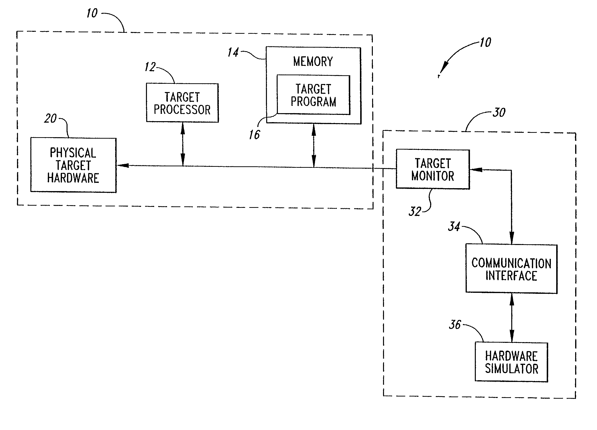
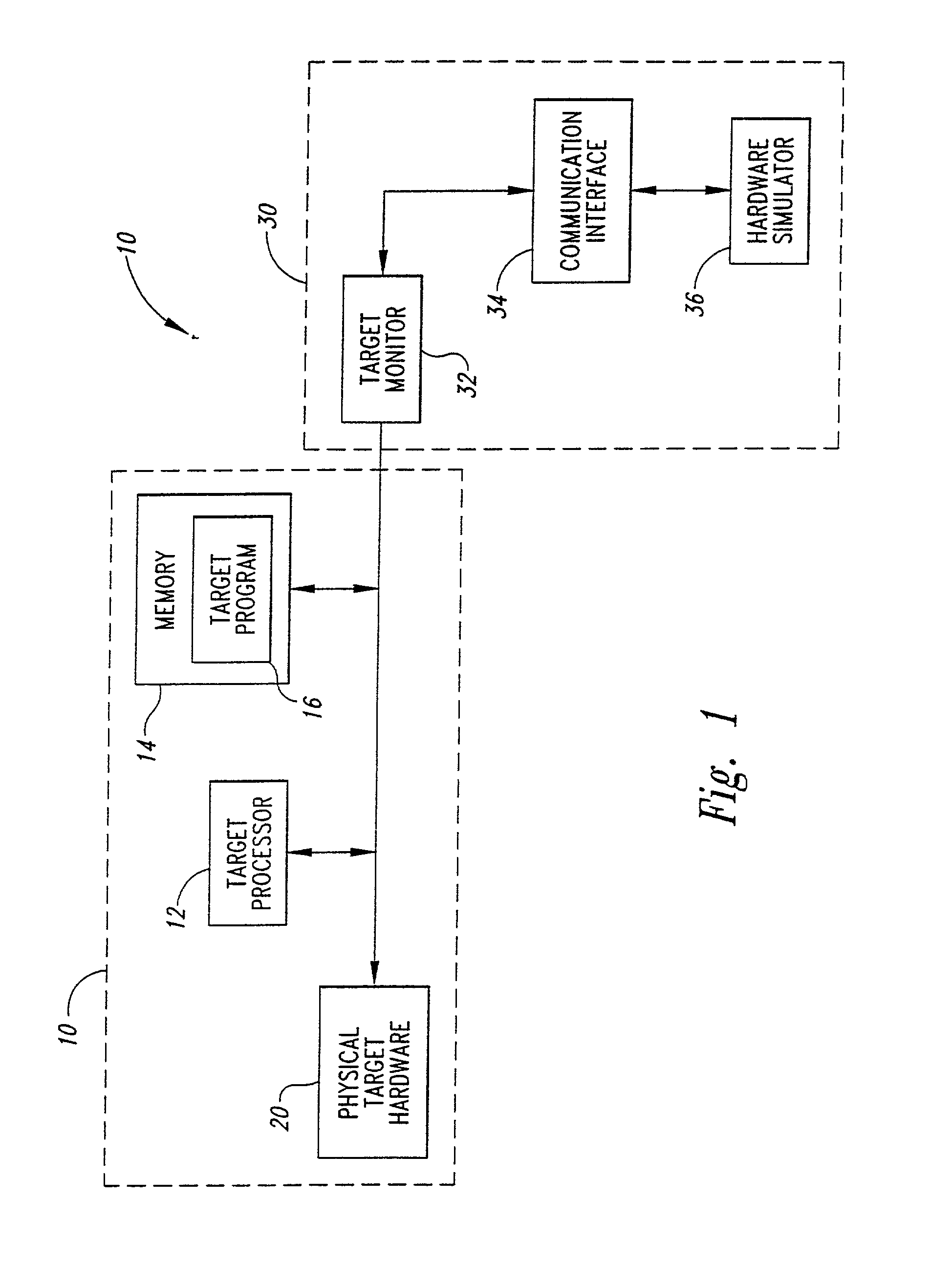
[0017]One embodiment of a system for testing embedded electronic systems is illustrated in FIG. 1. An embedded system 10 includes a target processor 12 coupled to a memory 14 that contains at least a target program 16 for execution by the target processor 12. The memory 14 may also include other program instructions and / or data for use by the target processor 12. The memory 14 may be read only memory (“ROM”), random access memory (“RAM”), or a combination of ROM and RAM.

[0018]Also coupled to the target processor 12 in the embedded system 10 is physical target hardware 20, which consists of the target hardware that has already been implemented. The remaining portion of the target hardware that is not included in the physical target hardware 20 is simulated, as explained below.

[0019]A system 30 for testing the embedded system 10 includes a target monitor 32, a communications interface 34, and a hardware simulator 36 that is coupled to the target monitor 32 through the communications i...


PUM


Abstract

A system for testing an embedded system containing a target processor executing a target program and target hardware that has a physical portion and a simulated portion. A target monitor determines when the target processor is attempting to access simulated hardware. The address bus of the microprocessor is monitored to detect an address in the address space of the simulated hardware. Lack of an acknowledge signal from the physical hardware within a predetermined period after the target processor attempts to access the target hardware may also indicate simulation. A bus capture circuit captures output signals on the bus connections of the target processor and converts the output signals to output data. The output data is then coupled through a communications interface to a hardware simulator. The hardware simulator processes the data in the same manner that the physical hardware would respond to signals corresponding to the output data.

Description

CROSS-REFERENCE TO RELATED APPLICATION[0001]This application is a divisional of U.S. patent application Ser. No. 09 / 024,324, filed Feb. 17, 1998 now U.S. Pat. No. 6,298,320.TECHNICAL FIELD[0002]The present invention relates generally to testing software and hardware in embedded systems, and, more specifically, to a system and method for testing software and hardware in embedded systems in which the hardware may be wholly or partially simulated.BACKGROUND OF THE INVENTION[0003]The use of computer simulation has become widespread in many areas, such as circuit design. The cost of manufacturing an integrated circuit is extremely high, and it is desirable that the hardware incorporated into the integrated circuit be tested prior to the actual fabrication of the integrated circuit. To that end, integrated circuit manufacturers often use simulators to test the hardware and the software intended to be executed by the hardware. The desired hardware design is known as the “target hardware,” ...

Claims


Application Information

Patent Timeline
IPC IPC(8): G06F17/50G06F11/22G06F11/26
CPCG06F11/261
Inventor BUCKMASTER, MICHAEL R.BERGER, ARNOLD S.
Owner NXP USA INC
Why Eureka
Eureka Blog
Learn More