
Method and apparatus for configuration of automated debug of in-circuit tests

a technology of in-circuit tests and configuration methods, applied in the direction of testing circuits, instruments, nuclear elements, etc., can solve the problems of inability to determine the status of the device or component under test, faulty generated tests, and inability to design and test these integrated circuits

Inactive Publication Date: 2006-08-08
AGILENT TECH INC
View PDF2 Cites 9 Cited by
  • Summary
  • Abstract
  • Description
  • Claims
  • Application Information

AI Technical Summary

Benefits of technology

The present invention provides a method and apparatus for creating viable tests by binding knowledge and experience into a reusable rule format and storage framework. This involves configuring an automated test associated with a component to be tested on a tester by creating first, second, and third associations between validation criteria, actions, and rules. These associations are maintained in a knowledge framework to be reused for configuration of various tests. The invention allows for efficient and effective test creation by extracting relevant information from users through a user interface and storing it in a knowledge framework.

Problems solved by technology

With the improvements in speed and density of integrated circuits, the cost and complexities of designing and testing these integrated circuits has dramatically increased.
However, for various reasons, it is often the case that a fairly significant percentage (e.g., 20%) of the automatically generated tests are faulty in that when executed on a known good device under test, the test is unable to determine the status of the device or component under test.
Clearly, for devices under test that include thousands of components, this results in a large number of tests that must be manually repaired.
However, with such a large number of faulty tests to repair, a large (and therefore, very costly) amount of time may be spent in test debug and optimization rather than in actual testing of the device itself.

Method used


Image

  • Method and apparatus for configuration of automated debug of in-circuit tests
  • Method and apparatus for configuration of automated debug of in-circuit tests
  • Method and apparatus for configuration of automated debug of in-circuit tests

Examples


Embodiment Construction

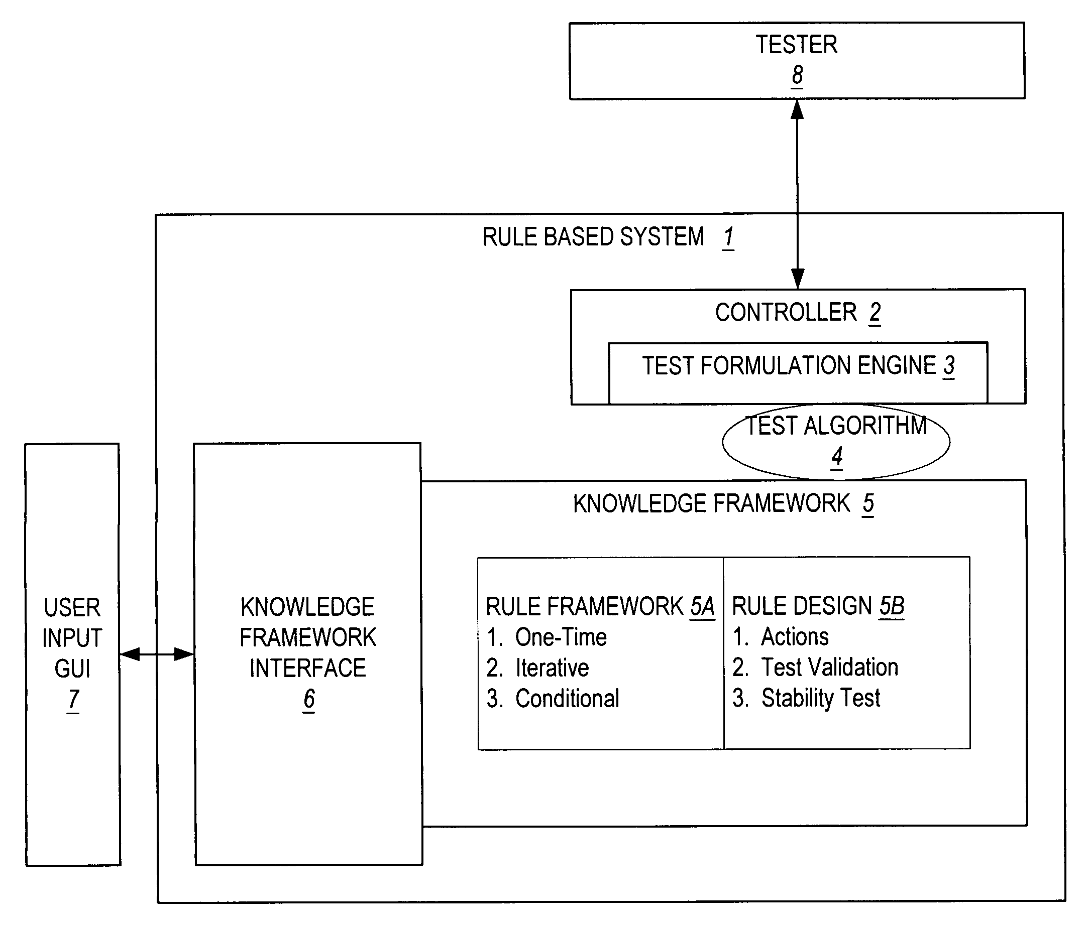
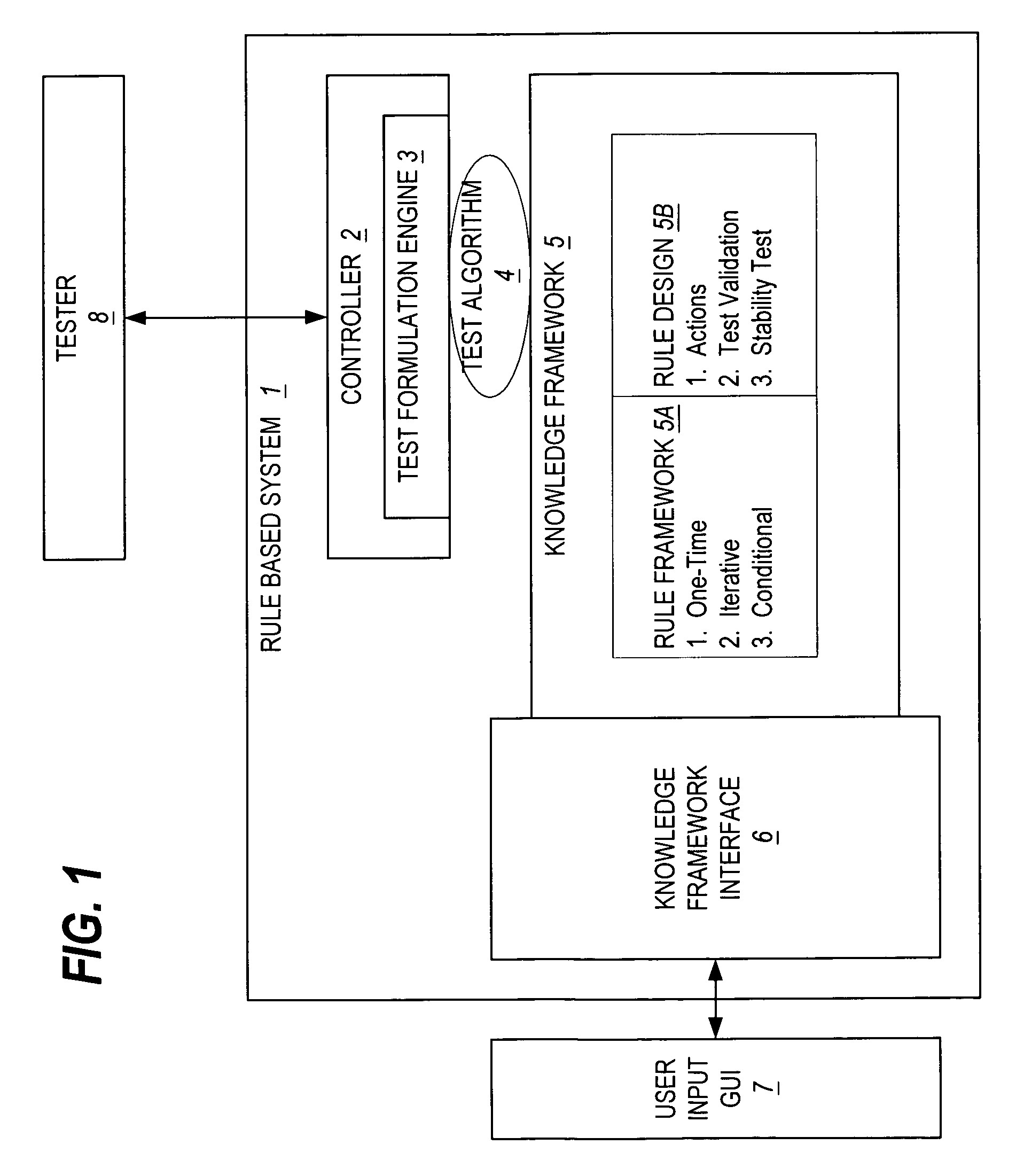
[0024]Turning now to the invention, FIG. 1 shows a rule based system 1 which utilizes the invention. As illustrated, the rule based system 1 includes three main components, namely a rule-based system controller 2, a knowledge framework 5, and a knowledge framework interface 6 / user input graphical user interface (GUI) 7. The rule-based system controller 2 controls the interaction between a tester 8 and the rule-based system 1. The knowledge framework 5 contains the test knowledge, including rule framework 5a and rule design 5b. The knowledge framework interface 6 and user input GUI 7 are together used to capture user knowledge into assns of rule sets, rules, and actions.

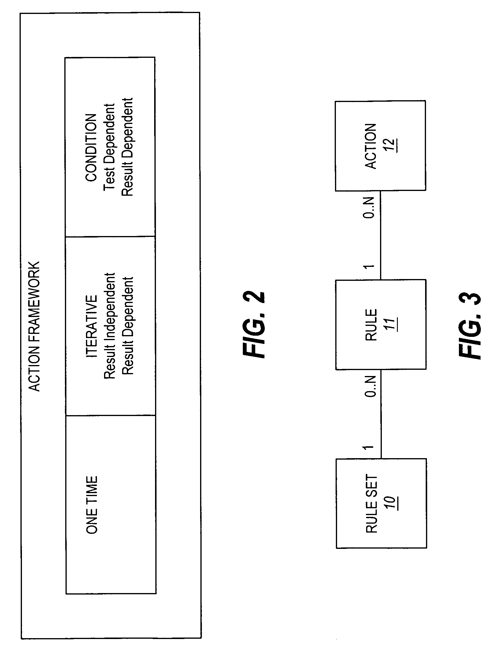
[0025]FIG. 2 illustrates a preferred embodiment of the action framework. As illustrated, there are three main categories of actions, namely one-time, iterative and condition. The “one-time” class is a one-off test that is independent of the testing environment and it is similar to a normal manual test.

[0026]Within the...


PUM


Abstract

A method for configuring an automated in-circuit test debugger is presented. The novel test debug and optimization configuration technique configures expert knowledge into a knowledge framework for use by an automated test debug and optimization system for automating the formulation of a valid stable in-circuit test for execution on an integrated circuit tester. In a system that includes a rule-based controller for controlling interaction between the test-head controller of an integrated circuit tester and an automated debug system, the invention includes a knowledge framework and a rule-based editor. The knowledge framework stores test knowledge in the representation of rules that represent a debugging strategy. The rule-based editor facilitates the use of rules as knowledge to debug or optimize an in-circuit test that is to be executed on the integrated circuit tester.

Description

BACKGROUND OF THE INVENTION[0001]The increasing reliance upon computer systems to collect, process, and analyze data has led to the continuous improvement of the system assembly process and associated hardware. With the improvements in speed and density of integrated circuits, the cost and complexities of designing and testing these integrated circuits has dramatically increased. Currently, large complex industrial integrated circuit testers (commonly referred to in the industry as “Automated Test Equipment” or “ATE”) perform complex testing of integrated circuit devices, such as integrated circuits, printed circuit boards (PCBs), multi-chip modules (MCMs), System-on-Chip (SOC) devices, printed circuit assemblies (PCAs), etc. The tests that must be performed may include, among others, in-circuit test (ICT), functional test, and structural test, and are designed to verify proper structural, operational, and functional performance of the device under test (DUT).[0002]An example of an ...

Claims


Application Information

Patent Timeline
Patent Type & Authority Patents(United States)
IPC IPC(8): G06F7/02
CPCG01R31/2834G01R31/2846G01R31/2843
Inventor LOH, AIK KOONWAI, KEEN FUNGTAN, TIAM HOCKWILLIAMS, ROY H.WHANG, DANIEL Z.LOW, CHEN NIYUAN, ELLIS
Owner AGILENT TECH INC
Learn More