Low noise, electric field sensor

a technology of electric field sensor and low noise, which is applied in the field of low noise, electric field sensor, electronic circuit, can solve the problems of not solving all of the problems, affecting the coupling between the antenna and the amplifier, and affecting the performance of the amplifier,

Inactive Publication Date: 2006-08-08
QUANTUM APPLIED SCI & RES
View PDF71 Cites 34 Cited by
  • Summary
  • Abstract
  • Description
  • Claims
  • Application Information

AI Technical Summary

Benefits of technology

[0009]In overview, for the operation of the system, the input potential is taken from the guard. The input bias current in this input potential is then separated from the input signal to establish a corrective signal. Next, the corrective signal is used to alter the input potential at the input port of the amplifier. The result is that the input bias current is effectively eliminated from the amplifier input. Consequently, the ultrahigh impedance of the antenna can be matched with the ultrahigh impedance of the amplifier, and the amplifier's operation can be stabilized.
[0012]In the specific case where a differential amplifier is used, a combination of the embodiments mentioned above can be incorporated. Specifically, the input potential at the guard can be fed through a low pass filter to the additional input port of the amplifier. As discussed above, this will allow the input bias current to be used for canceling itself in the amplifier. At the same time, the input potential at the guard can be passed through a capacitor to a high impedance path that is connected between the capacitor and the input port of the amplifier. As discussed above, this circuitry allows the input bias current in the input potential to be shunted to ground and to thereby remove the input bias current from the input potential.

Problems solved by technology

The problem here, however, is that any resistive path of even very high resistance value at the amplifier input, will also act as a short to ground.
This will then effectively insert an RC filter into the amplifier input circuit that will adversely affect the coupling between the antenna and the amplifier.
Although the removal of resistive paths from an amplifier input may improve the coupling efficiency of the amplifier, it will not necessarily solve all of the problems that are presented by an ultrahigh input impedance amplifier.
Specifically, the removal of resistive paths from the amplifier input still does not account for the amplifier's inevitable input bias current.
In any event, unless the input bias current is somehow accounted for, it will flow onto the amplifier input capacitance and onto the source capacitance, and thereby produce a continual drift in the input signal level.
This can then lead to saturation of the amplifier.

Method used


Image

  • Low noise, electric field sensor
  • Low noise, electric field sensor
  • Low noise, electric field sensor

Examples


Embodiment Construction

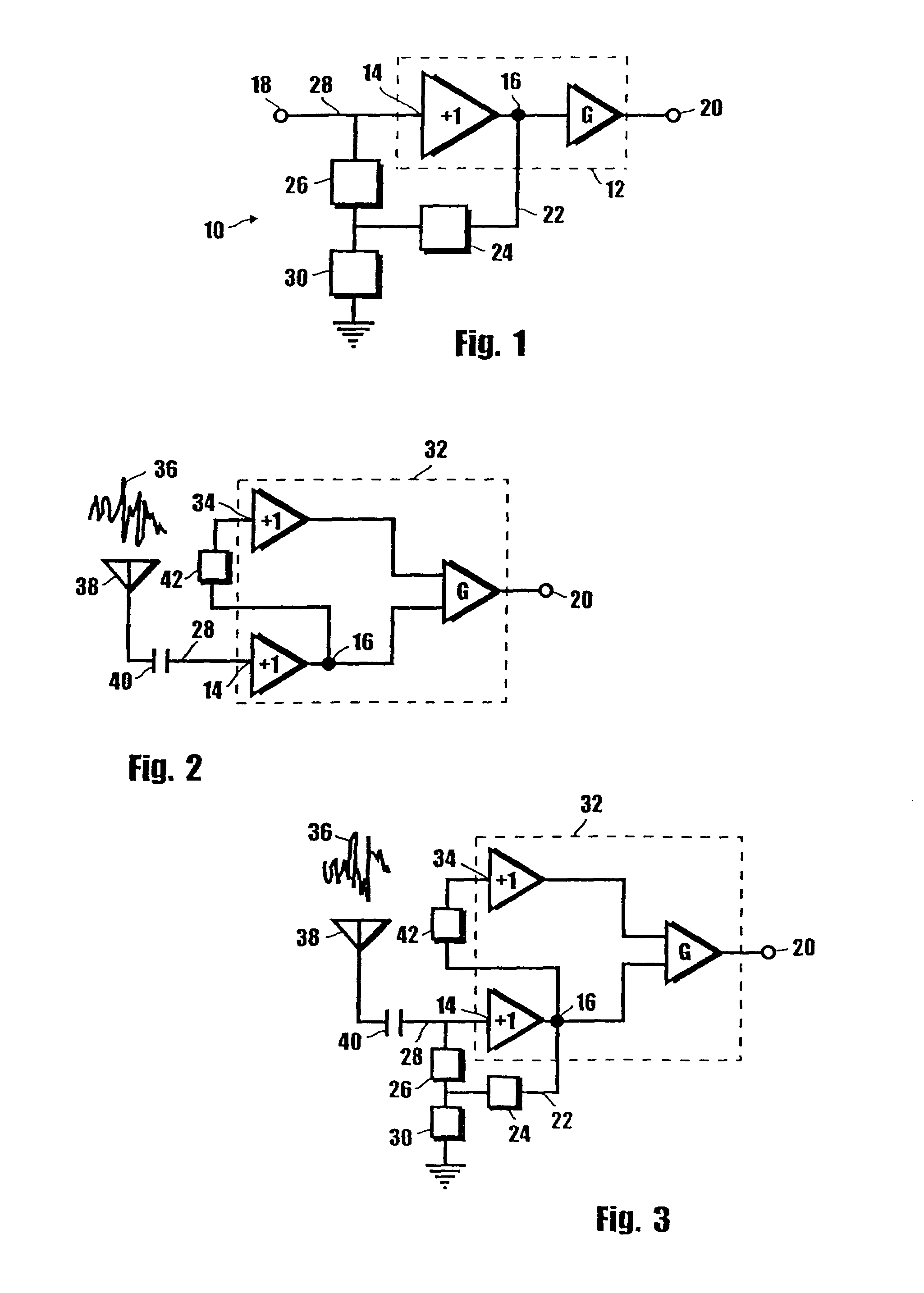
[0021]Referring initially to FIG. 1, a circuit in accordance with the present invention is shown and is generally designated 10. As shown, the circuit 10 includes an amplifier 12 which has an input port 14 and a guard 16. As contemplated for the present invention, the guard 16 is of a type that is known to the skilled artisan. Essentially, the guard 16 provides a voltage that can be used to minimize leakage of the signal to the environment during passage to the input port 14 of the amplifier 12. Importantly, the input port 14 and the guard 16 will have the same input potential.

[0022]In accordance with the normal operation of an amplifier, the amplifier 12 receives an input signal 18; amplifies the input signal 18 by a gain, G; and then provides the amplified input signal 18 as an output 20. The present invention, however, contemplates that the input signal 18 is received from a source having an ultrahigh impedance which can disrupt the normal operation of an amplifier.

[0023]As is we...


PUM


Abstract

A system for measuring a free space electric field includes an ultrahigh impedance antenna positioned in the electric field to generate a signal from the electric field. An amplifier having an input port is provided to amplify the signal. The amplifier generates an input bias current which combines with the signal to create an input potential at the input port. An electrical circuit connects the input port to a ground connection and includes at least one circuit element for controlling the input potential to stabilize the signal at the input port.

Description

[0001]This application is a continuation-in-part of U.S. patent application Ser. No. 09 / 783,858 filed Feb. 13, 2001, now U.S. Pat. No. 6,686,800, issued Feb. 3, 2004. The contents of U.S. patent application Ser. No. 09 / 783,858 are incorporated herein by reference.FIELD OF THE INVENTION[0002]The present invention pertains generally to electronic circuits. More specifically, the present invention pertains to electronic circuits which are useful for stabilizing the operation of an amplifier. The present invention is particularly, but not exclusively, useful as a circuit which removes the input bias current from the input potential to an ultrahigh input impedance amplifier in order to stabilize the amplifier's operation.BACKGROUND OF THE INVENTION[0003]It is well known that free space electric fields are emitted from many different types of sources. For example, it is known that organs in the human body, such as the heart and the brain, produce electric fields. Also, electric fields are...

Claims


Application Information

Patent Timeline
IPC IPC(8): H03F3/45G01R31/02G01R29/08H01QH03F1/08H03F1/26H03F1/30H03F1/34H03F1/56
CPCG01R29/0871H03F1/08H03F1/26H03F1/34H03F1/56H03F1/30H03F2200/261H03F2200/153
Inventor KRUPKA, MICHAEL ANDREW
Owner QUANTUM APPLIED SCI & RES
Why Eureka
Try Eureka