
Method for fabricating micro-structures with various surface properties in multi-layer body by plasma etching

a plasma etching and micro-structure technology, applied in the direction of fluid speed measurement, insulating layer/substrates working, chemical vapor deposition coating, etc., can solve the problems of low tolerance, high production cost, and important decrease in analysis tim

Inactive Publication Date: 2006-08-08
DIAGNOSWISS
View PDF8 Cites 22 Cited by
  • Summary
  • Abstract
  • Description
  • Claims
  • Application Information

AI Technical Summary

Benefits of technology

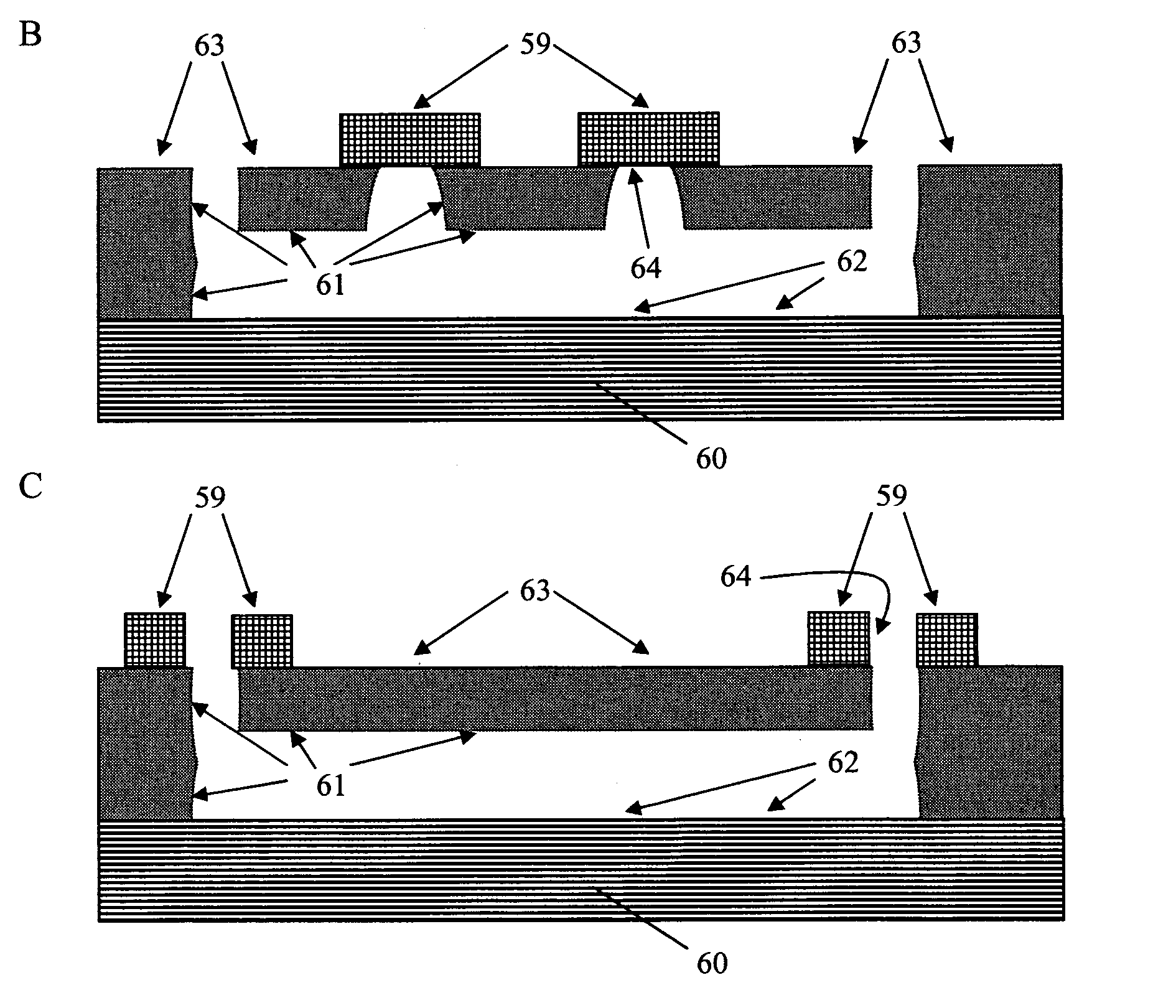
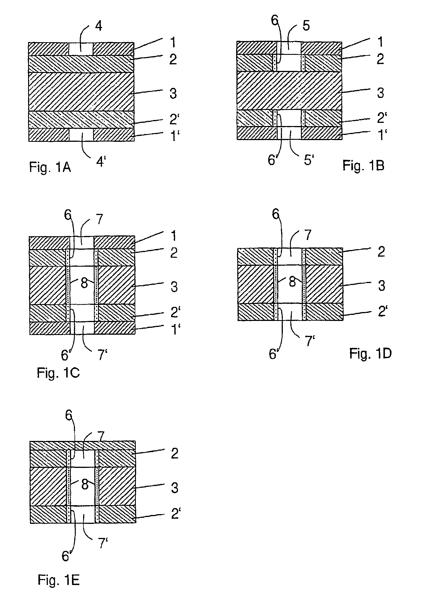
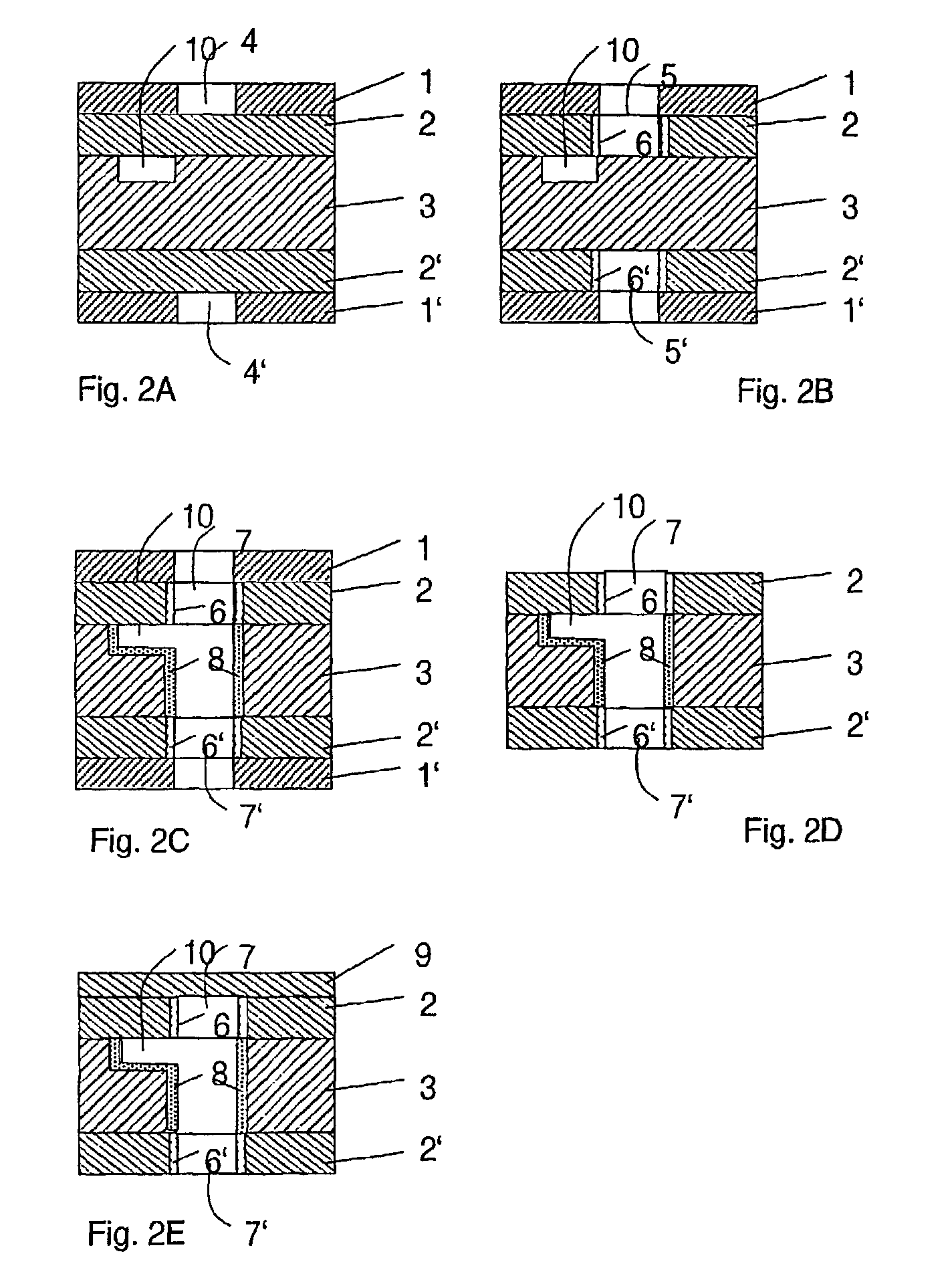
[0032]According to the present invention, an etching method for manufacturing micro-structures or openings in a multilayer body made of selected materials is provided, wherein the surface properties of the layers are controlled individually and preferably simultaneously control, so that conduits, grooves, reservoirs, holes and so forth are formed and exhibit various surface properties allowing further functionalisation of selected surfaces as well as fluid handling.

Problems solved by technology

In many cases, the decrease in analysis time is also an important issue e.g. in medical diagnostics, where the time factor may signify a fatal issue for the patient.
Etched capillaries are then generally sealed by thermal bonding with a glass covert The bonding technique in particular is labour and technology intensive and thermal bonding requires temperatures between 600–1000° C. This bonding technique has a very low tolerance of defect or presence of dust and requires clean room conditions for the fabrication, which means that the production is very expensive.
As different species exhibit different diffusion coefficients, efficient mixing becomes problematic, and this is often presented as a serious limitation for the wider use of microfluidic in total analysis systems.

Method used


Image

  • Method for fabricating micro-structures with various surface properties in multi-layer body by plasma etching
  • Method for fabricating micro-structures with various surface properties in multi-layer body by plasma etching
  • Method for fabricating micro-structures with various surface properties in multi-layer body by plasma etching

Examples


Embodiment Construction

[0060]The term “micro-structure”, as used herein, means and refers to a single micro-channel, an array of micro-channels or a network of interconnected micro-channels not limited in shape but having a cross-section enabling micro-fluidic manipulations. In accordance to the present invention, these “micro-structures” are usually formed in e.g. a plate, a planar substrate or the like, and they are usually made in at least two layers, one containing the desired micro-structure pattern and a second one serving as sealing component.

[0061]The term “openings”, as used herein, means and refers to hollow passages or spaces. These openings include for example reaction chambers, reservoirs, wells and the like. They can stand alone or can be positioned at either end of a channel. When such openings stand alone, they can for instance be used for reagent introduction, mixing, incubation, washing, reaction, detection and the like, as required in e.g. homogeneous assays. When connected to a channel...


PUM

PropertyMeasurementUnit
Thicknessaaaaaaaaaa
Lengthaaaaaaaaaa
Thicknessaaaaaaaaaa

Abstract

The technology is based on the anisotropic plasma etching of organic polymer sheets partially protected by a metallic mask. The originality of the process is to pattern the surface properties by the same physical means as the one used for the three dimensional fabrication and simultaneously to this fabrication. Surface properties means, but are not limited to hydrophobicity, hydrophilicity, conductivity, reflectability, rugosity and more precisely the chemical and / or physical state of the surface. It is also possible to generate the desired fonctionalities, for instance carboxylic acid, ester, ether, amid or imid, during the etching process. The patterning of the different properties may be achieved by two different techniques that may be used separately or simultaneously.

Description

CLAIM FOR PRIORITY[0001]This application makes reference to, incorporates the same herein, and claims all benefits accruing under 35 U.S.C. §§119 from a provisional application for METHOD FOR FABRICATING MICRO-STRUCTURES WITH VARIOUS SURFACE PROPERTIES I MULTILAYER BODY BY PLASMA ETCHING earlier filed under 35 U.S.C. §111(b) in the United States Patent & Trademark Office on the 31 Jan. 2000 and there duly assigned Ser. No. 60 / 179,334.CROSS-REFERENCE TO RELATED APPLICATIONS[0002]This application refers to and relates to a Patent Cooperation Treaty application entitled METHOD FOR FABRICATING MICRO-STRUCTURES WITH VARIOUS SURFACE PROPERTIES IN MULTI-LAYER BODY BY PLASMA ETCHING filed in the World Intellectual Property Organization via the Swiss Federal Institute of Intellectual Property on the 30th day of Jan. 2001, and there assigned Application No. PCT / CH01 / 00070, and later published as publication No. WO 01 / 56771 A2 on the 9th day of Aug. 2001.FIELD OF THE INVENTION[0003]The present...

Claims


Application Information

Patent Timeline
IPC IPC(8): B81C1/00B01F13/00B01L3/00B29C59/14B81B1/00G01N27/447G01N30/28G01N30/60H05K3/00
CPCB01F13/0059B81C1/00206B01L3/502707B29C59/14G01N27/44791H05K3/0041B81C1/00119B01J2219/0086B01L2200/12B29C2059/023B29L2009/00G01N30/6095G01N2030/285H05K3/002H05K3/0032H05K2203/0554B01J2219/00828B01F33/30H01B13/00
Inventor SCHMIDT, WALTERREYMOND, FREDERICROSSIER, JOEL S.
Owner DIAGNOSWISS
Learn More