Electrical connector (receptacle) with easily removable bottom

a technology of electric connectors and bottoms, which is applied in the direction of fixed connections, contact members penetrating/cutting insulation/cable strands, printed circuits, etc., can solve the problems of difficult or even impossible to remove the cover, and achieve the effect of easy removal

Active Publication Date: 2006-08-08
MILL MAX MFG CORP
View PDF6 Cites 15 Cited by
  • Summary
  • Abstract
  • Description
  • Claims
  • Application Information

AI Technical Summary

Benefits of technology

[0004]The present invention teaches, in a number of embodiments, a novel structure and function of an array of connectors fastened to a planar insulator, usually formed of a high temperature thermoplastic. The planar insulator has a pattern of substantially cylindrical openings formed therein into which is inserted a machined copper alloy sleeve which is plated with tin or tin-lead alloy. The sleeve itself is a hollow substantially cylindrical tube with a multi-finger spring contact inserted near one (usually called the upper end). The spring contact itself is plated with gold, tin, tin-lead or other malleable electrically conductive material. At the far end of the cylindrical tube is fixed a plug of “kraft paper” to function as a barrier, made from substantially pure wood pulp with no fillers. The cylindrical tube of the sleeve grips the kraft paper barrier sufficiently for it to remain in place during the processing cycle when the copper alloy sleeve is soldered to the circuit board. The “kraft paper” is stable and unaffected by the temperature to which the solder is heated to become fluid and can be easily removed by the insertion of a connector lead into the sleeve.

Problems solved by technology

If that happens it is difficult or even impossible to remove the cover.

Method used


Image

  • Electrical connector (receptacle) with easily removable bottom
  • Electrical connector (receptacle) with easily removable bottom
  • Electrical connector (receptacle) with easily removable bottom

Examples


Embodiment Construction

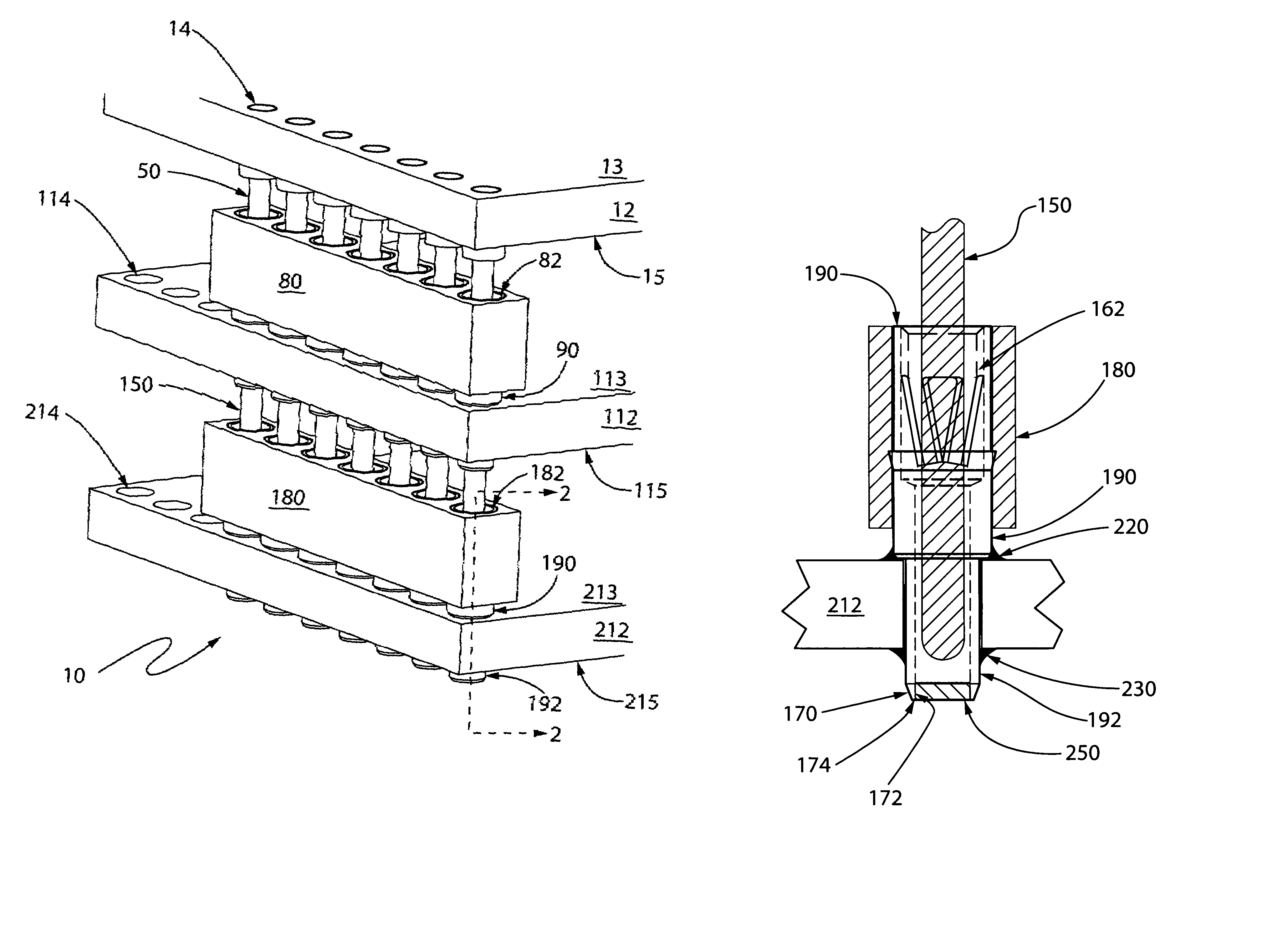
[0007]FIG. 1 is perspective view of a first embodiment of the present invention showing by the number 10, by way of example and not limitation, a three-layer circuit board assembly. The circuit boards are shown as parts 12, 112, 212 in which like parts have like numbers preceded by the numeral 1 or 2. Each circuit board has an array of plated through orifices 14, 114, 214 respectively. Interconnecting the circuit boards are sockets 80, 180 with interconnection pins 50, 150.

[0008]Each circuit board has an upper and lower surface 13, 15, 113, 115, 213, 215 respectively as shown in FIG. 1. The sockets 80, 180 have through channels 82, 182 into which are inserted interconnection pins 50, 150.

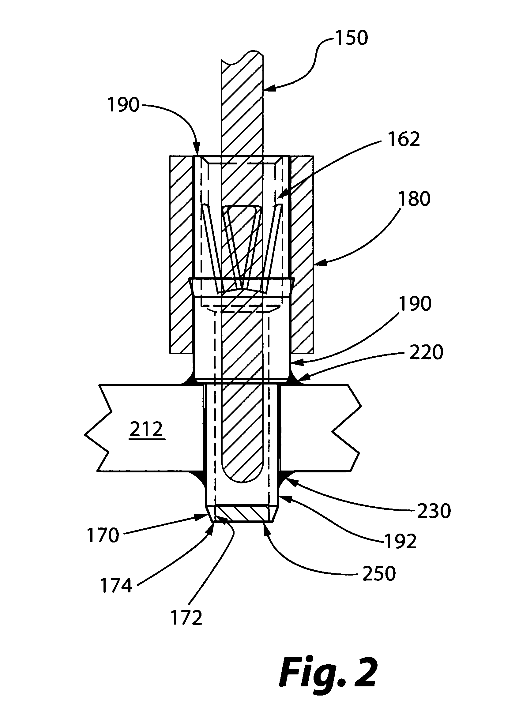
[0009]Looking at the detail shown in FIG. 2 for the socket and interconnection pin portion of the invention is the socket insulator having a socket sleeve 190 inserted there through. A multi-finger spring contact 62, 162 formed from spring temper copper alloy which is inserted into the upper end of ...


PUM


Abstract

A structure of an array of connectors fastened to a planar insulator, usually formed of a high temperature thermoplastic. The planar insulator has a pattern of substantially cylindrical openings formed therein into which is inserted a machined copper alloy sleeve which is plated with tin or tin-lead alloy. The sleeve itself is a hollow substantially cylindrical tube with a multi-finger spring contact inserted near one (usually called the upper end). The spring contact itself is plated with gold, tin, tin-lead or other malleable electrically conductive material. At the far end of the cylindrical tube is fixed a plug of “kraft paper” to function as a barrier, made from substantially pure wood pulp with no fillers. The cylindrical tube of the sleeve grips the kraft paper barrier sufficiently for it to remain in place during the processing cycle when the copper alloy sleeve is soldered to the circuit board. The “kraft paper” is stable and unaffected by the temperature to which the solder is heated to become fluid and can be easily removed by the insertion of a connector lead into the sleeve.

Description

BACKGROUND OF THE INVENTION[0001]The present invention relates to a novel electrical connector that is attached to a printed circuit board by soldering, in which the connector is a receptacle usually, but not necessarily, arranged in an array, such as, a single row, dual row, triple row, dual-in-line, pin grid array or other configuration of grid. The receptacle has placed or formed within it a spring contact for mechanically gripping another connector which will be inserted into it. One end of the connector is sealed by a removable material which is resistant to the heat of the soldering and at the same time protects the spring contact from contamination with flux and liquid solder.FIELD OF THE INVENTION[0002]The present invention relates to the field of electrical connectors arranged in arrays for soldering to a printed circuit board. Printed circuit boards with arranged arrays of contact receiving orifices are the sine qua non of modern electronics including but not limited to co...

Claims


Application Information

Patent Timeline
Patent Type & Authority Patents(United States)
IPC IPC(8): H01R12/00
CPCH01R4/028H01R9/096H01R12/52
Inventor SUTCLIFFE, ROGER F.
Owner MILL MAX MFG CORP
Why Eureka
Try Eureka