
Linked ring structures

Inactive Publication Date: 2006-08-08
M&J R&R GROSBARD
View PDF7 Cites 42 Cited by
  • Summary
  • Abstract
  • Description
  • Claims
  • Application Information

AI Technical Summary

Benefits of technology

[0005]The present invention comprises a novel structure and a novel method of manufacturing novel articulated rings in general and finger rings in particular. The novel articulated rings of the invention comprise cast links having pins which are an integral part of the casting rather than pins which are inserted and soldered into place afterward. This concept means that the articulated rings may be assembled with very close tolerances without the need to have skilled artisans position and drill holes for the insertion of pins. The precision of the spacing and the size of the spaces between articulated parts is a characteristic of the novel articulated bands of the invention. The articulated rings of the invention comprise two elements or more preferably three elements: a cast linkable connector element, a cast open connector link element and an optional wedge shaped element adapted to close said cast open connector link element.

Problems solved by technology

This method has a drawback in that it results in the formation of gaps between the links which are sized according to the size of the milling machine tool head used to cut them apart.
Each link has the same dimensions which limits the ability to size the ring in conformance with standard ring sizing specifications.
Drill and pin techniques which could be utilized to achieve close tolerances between links have not been attempted due to prohibitive cost concerns.
Even the current method of CNC production is far more expensive than our method because it produces great amounts of wasted materials e.g. precious metals such as gold, platinum and the like and requires skilled operators at the production level.
It has always been a problem to make an articulated band that exactly matches a common series of finger sizes.
If rings are made using this technique, the cost of a separate model using a fixed articulated band design makes the availability of a collection of articulated band rings too expensive for mass manufacturing and distribution.

Method used


Image

  • Linked ring structures
  • Linked ring structures
  • Linked ring structures

Examples


Embodiment Construction

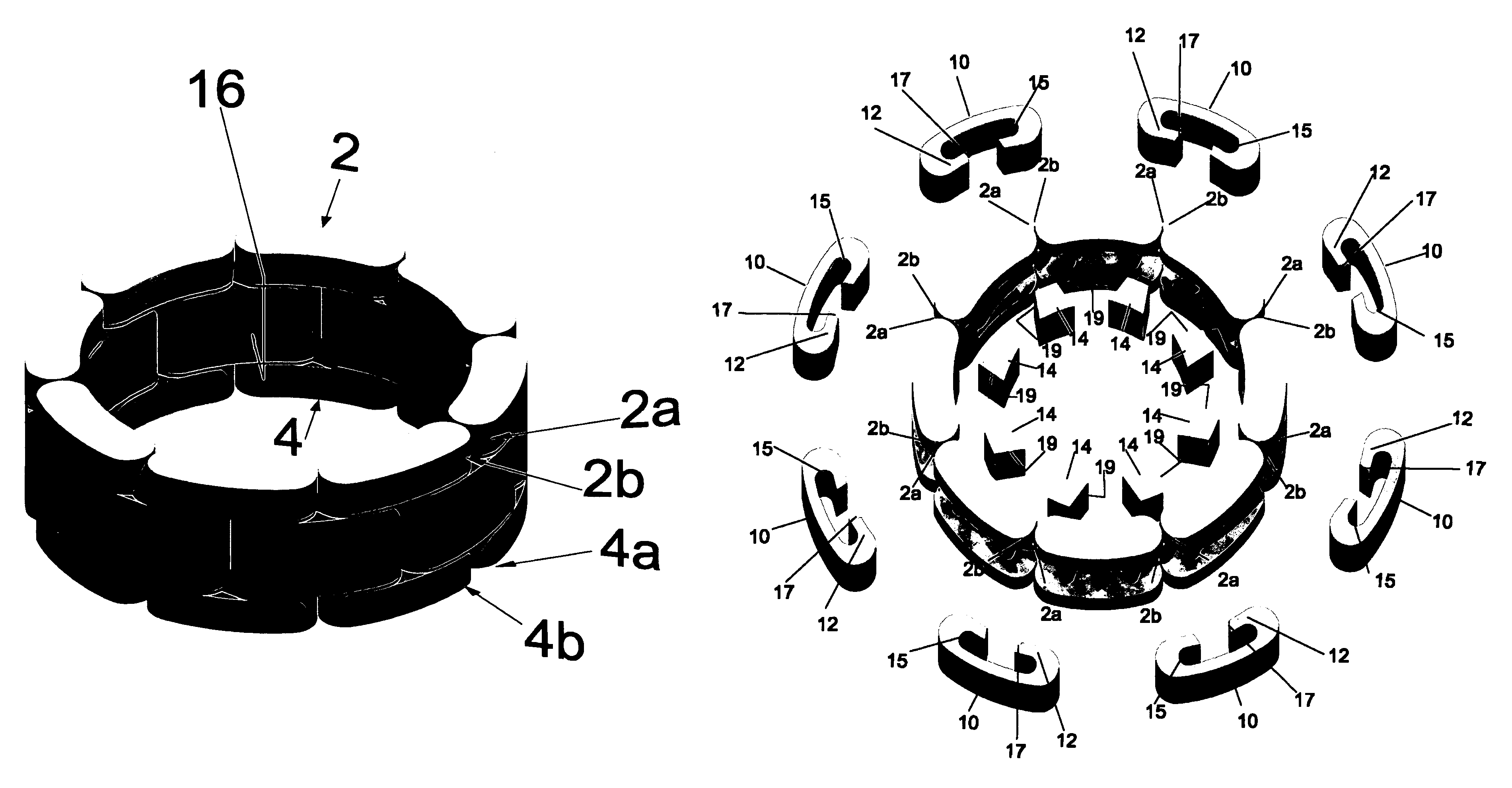
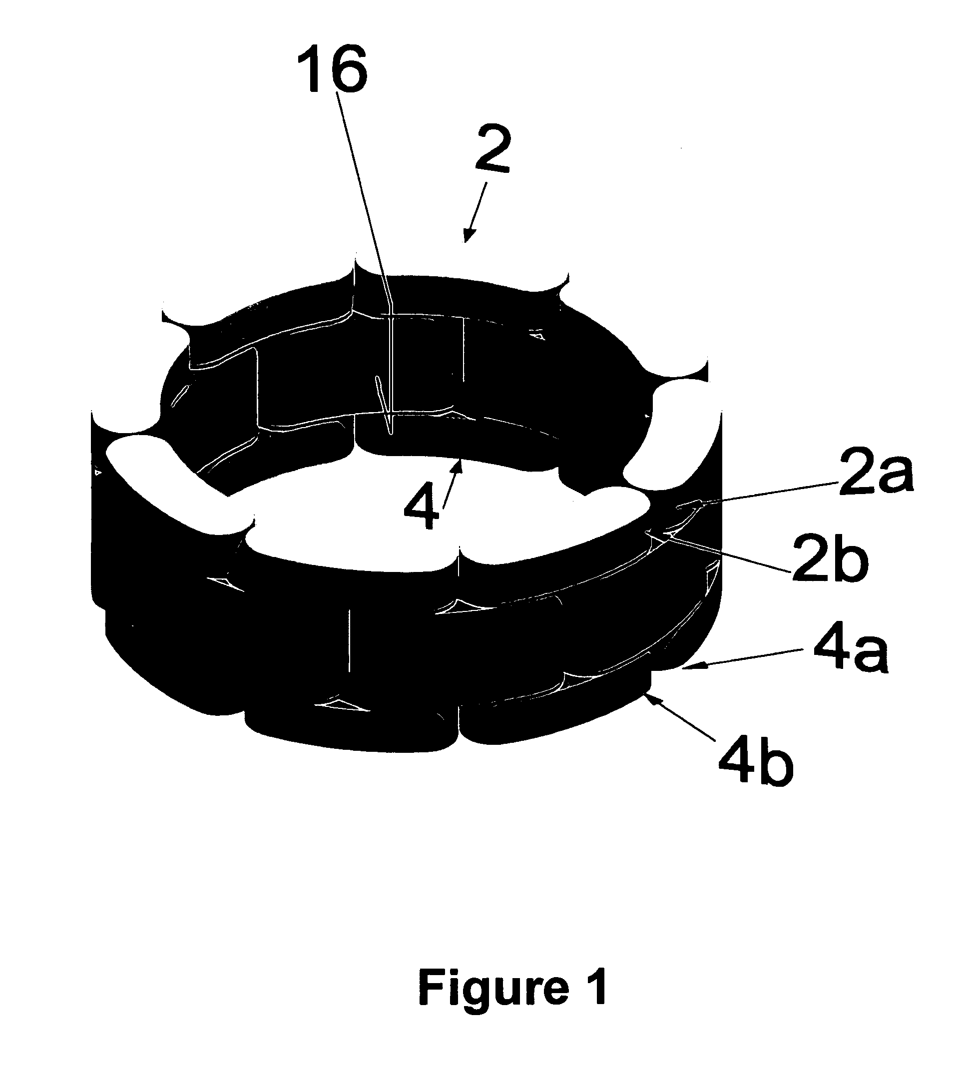
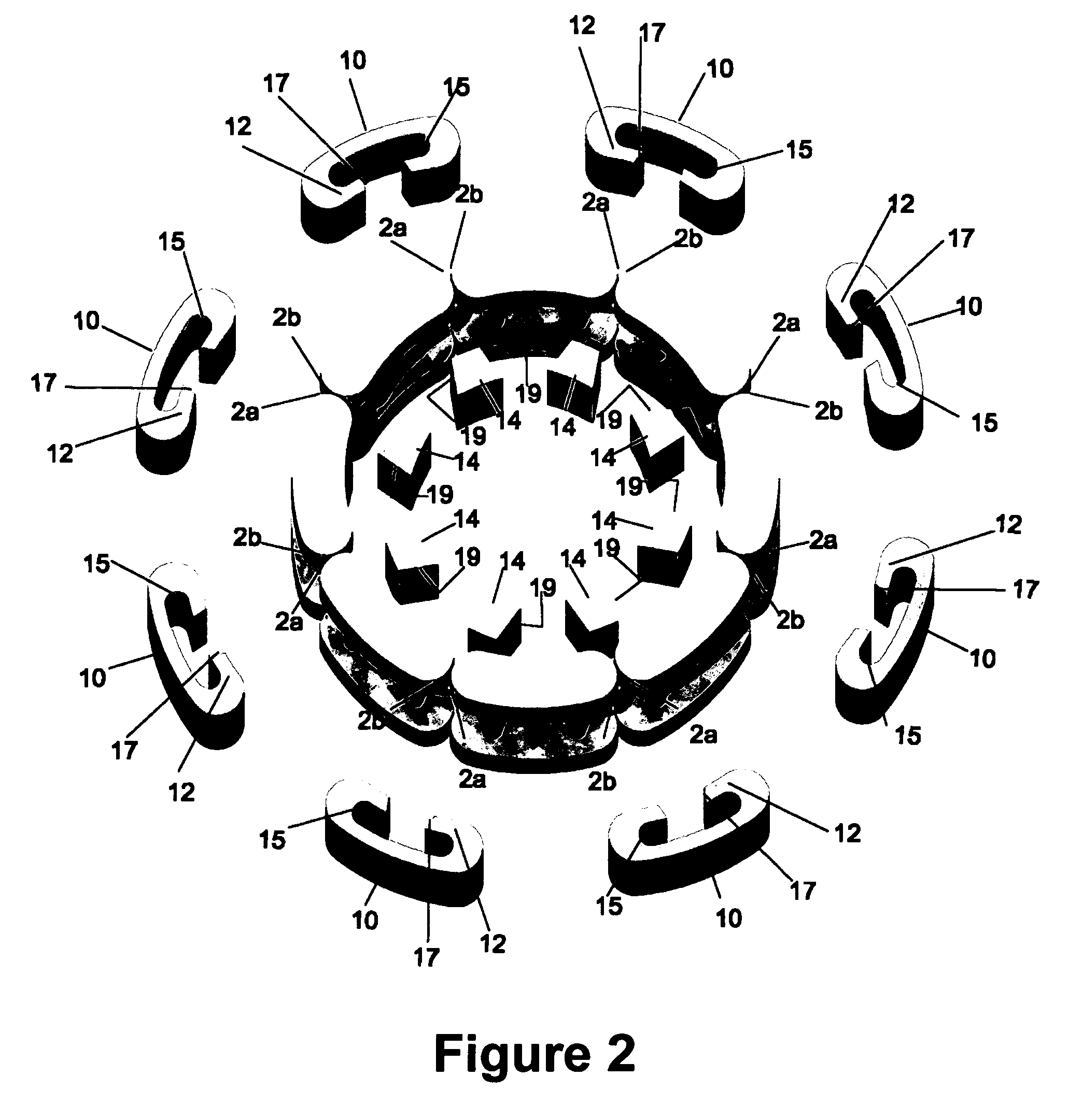
[0014]The present invention may be utilized to make articulated ring structures in general such as necklaces, watchbands, bracelets and articulated finger, thumb or toe rings in particular. The preferred material is metal, i.e. precious metal such as gold or platinum but other metals or thermoplastics or thermosets may be used to make articulated rings structures. As shown in the embodiment of FIG. 1, the articulated ring of the invention has three stacked layers. The top layer 2 and bottom layer 4 comprise a plurality of cast linkable connector 8 where the top layer 2 and bottom layer 4 of the articulated rings are connected to one another with rounded connecting posts that are not shown in FIG. 1 but are shown in FIG. 3 as posts 6 which are a part of the linkable connector casting 8. The cast linkable connector comprises a top layer 2; a bottom layer 4 and two molded in place posts 6 that connect the top layer 2 and the bottom layer 4 as shown in FIG. 3. The middle layer 5, compri...


PUM

PropertyMeasurementUnit
Structureaaaaaaaaaa

Abstract

An articulated ring, such as a finger ring is based on a cast linkable connector element and a cast open connector link element having hooked ends which are fitted to posts provide on said cast linkable connector element The invention also includes a novel method of making an articulated ring structure which is based on the steps of:(a) providing a plurality of cast linkable connector elements having a top layer and a bottom layer with the top layer and said bottom layer connected by two posts;(b) providing a plurality of cast connector link elements with two ends, with a hook at each of said ends, and each hook adapted to engage a post on the cast linkable connector; and(c) engaging each hook of each of the plurality of cast connector link elements with a post of two different cast linkable connector elements to form an articulated ring structure.

Description

BACKGROUND OF THE INVENTION[0001]In the prior art, two types of linked metal or articulated rings such as finger rings are known. The first and probably oldest type is simply a form of chain or chain mail made small enough for the finger and is capable of flexing on all three axes, These rings are made by bending and soldering wire into various kinds of intersecting loops. The second type flexes on only two axes and in this respect resembles a common steel watch band or a caterpillar type tractor tread. For convenience, this type of construction will be referred to as an “articulated band”.[0002]Articulated bands have been known at least since the beginning of the twentieth century and initially were made by a method of manufacture that required a skilled machinist with a hand lathe using links that were fabricated directly from tubular stock An alternate method involves the creation of model links via traditional jewelers techniques (carving of wax originals or filing of metal stoc...

Claims


Application Information

Patent Timeline
IPC IPC(8): F16G13/00B21L17/00B21L99/00
CPCA44C5/10A44C9/00B21L11/005B21L9/065Y10T29/49593F16G13/00
Inventor PASACH, LLOYD FRANK
Owner M&J R&R GROSBARD
Learn More