
Electrodeless discharge lamp

a discharge lamp and electrodeless technology, applied in the direction of discharge tube/lamp details, discharge tube luminescnet screens, electric discharge lamps, etc., can solve the problems of difficult, in the worst case, to start the lamp and maintain it lit, and similar problems, so as to reduce the interference effect, secure the start of the lamp, and reduce the effect of interferen

Inactive Publication Date: 2006-08-01
PANASONIC CORP
View PDF8 Cites 4 Cited by
  • Summary
  • Abstract
  • Description
  • Claims
  • Application Information

AI Technical Summary

Benefits of technology

"The present invention provides an electrodeless discharge lamp that reduces fixture interference while securing lamp startability by maintaining a high Q value of the induction coil. The lamp has a bulb with a reentrant portion protruding inwardly along the given direction and an induction coil arranged in the reentrant portion. The coil has a magnetic core and a winding wound around the magnetic core. The magnetic core has a length L in the given direction that is 1.05 times or more a length L' of the winding in the given direction, the length L being set to 41 mm or less. The lamp has a shape substantially axially symmetrical with respect to the given direction. The invention also provides a screw base for receiving commercial power and reduces the effect of interference while securing lamp startability by maintaining a high Q value of the induction coil. The lamp is lightweight and has a minimal magnetic core cost by restricting the axial length of the magnetic core to the minimum required size."

Problems solved by technology

The present inventors have found that when an electrodeless lamp operates on power at a relatively low driving frequency (e.g., 1 MHz or less), provision of a short-circuited metal ring as disclosed in Japanese Patent Application Laid-Open Publication No. 1995-262972 near the bulb will considerably reduce the starting pulse voltage generated in the induction coil during lamp startup, making it difficult, in the worst case, to start the lamp and maintain it lit.
The present inventors have also discovered that, even in the absence of such a metal ring, a similar problem will arise if the electrodeless lamp is used as attached to metallic lighting fixture, etc.
Thus, in the presence of a metal ring such as short-circuited metal ring or lighting fixture near the electrodeless lamp, the starting pulse voltage generated in the induction coil will decline considerably, making it difficult, in the worst case, to start the lamp and maintain it lit.
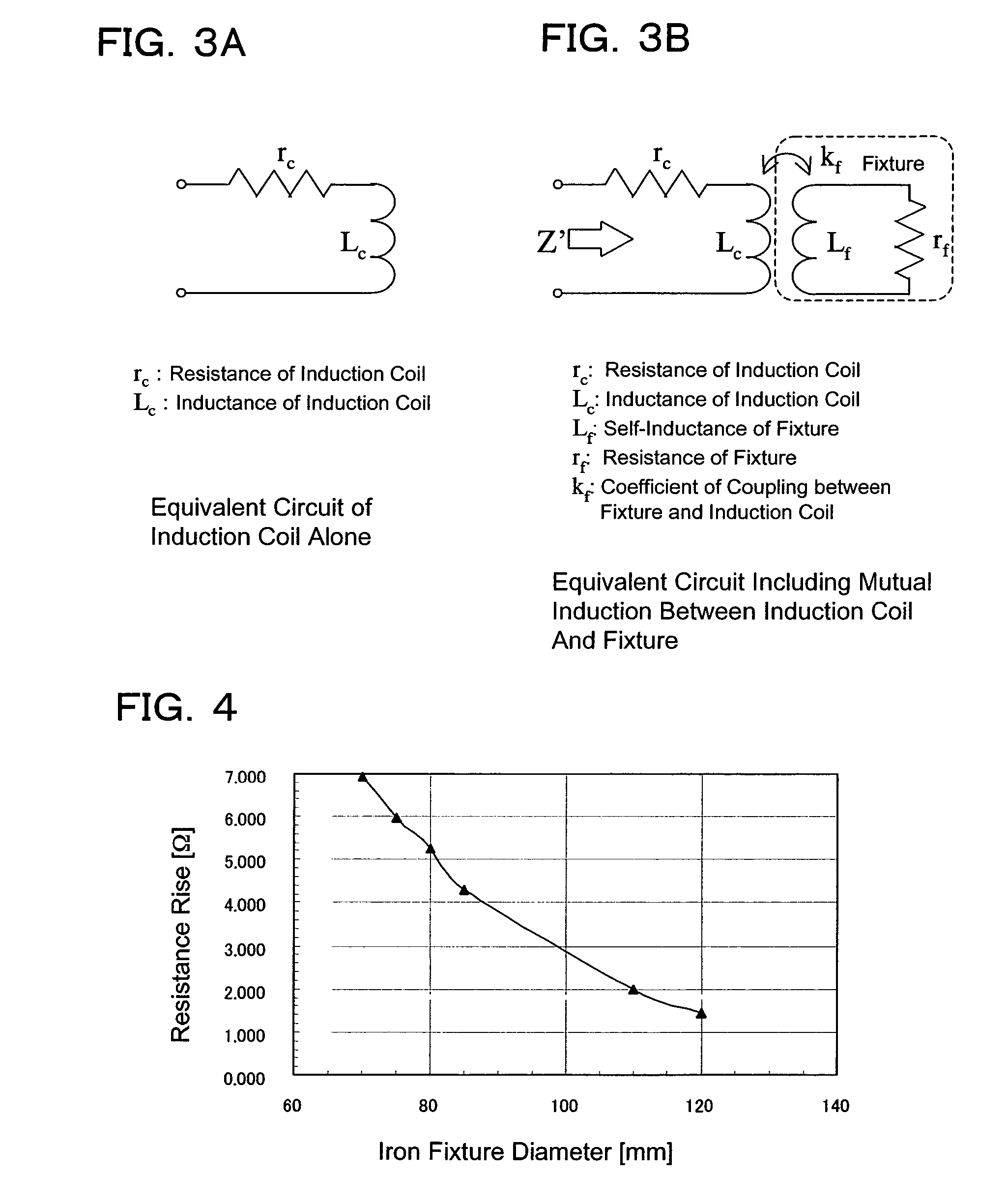
On the other hand, if the distance is close between the metal portion of the lighting fixture and the induction coil, mutual induction will unavoidably increase, reducing the Q value of the induction coil.
This results in difficulties in generation of the starting voltage at both ends of the induction coil—a voltage required to initiate electric discharge, possibly deteriorating the startability of the lamp.
Thus, depending on the magnitude of mutual inductance in fixture interference, the starting pulse voltage, generated in the induction coil during lamp startup, will decrease considerably, making it difficult, in the worst case, to start the lamp and keep it lighting.
As described earlier, this problem of lamp startability is prominent if the high-frequency power used for discharge is low in frequency (driving frequency).

Method used


Image

  • Electrodeless discharge lamp
  • Electrodeless discharge lamp
  • Electrodeless discharge lamp

Examples


Embodiment Construction

[0039]An embodiment of an electrodeless discharge lamp according to the present invention will now be described with reference to the accompanying drawings.

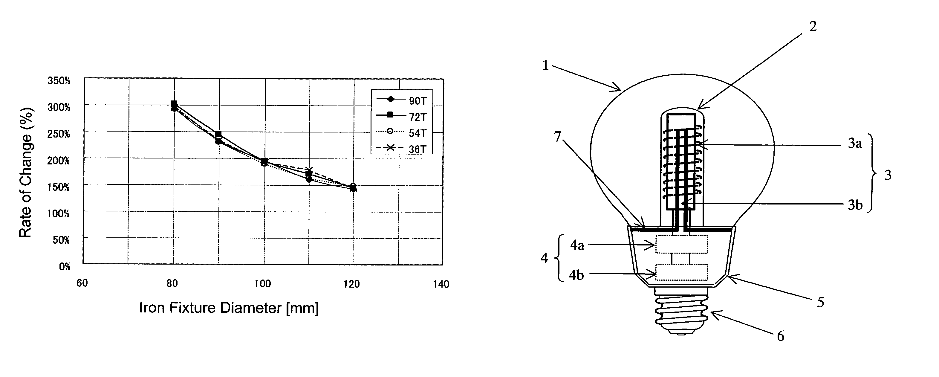
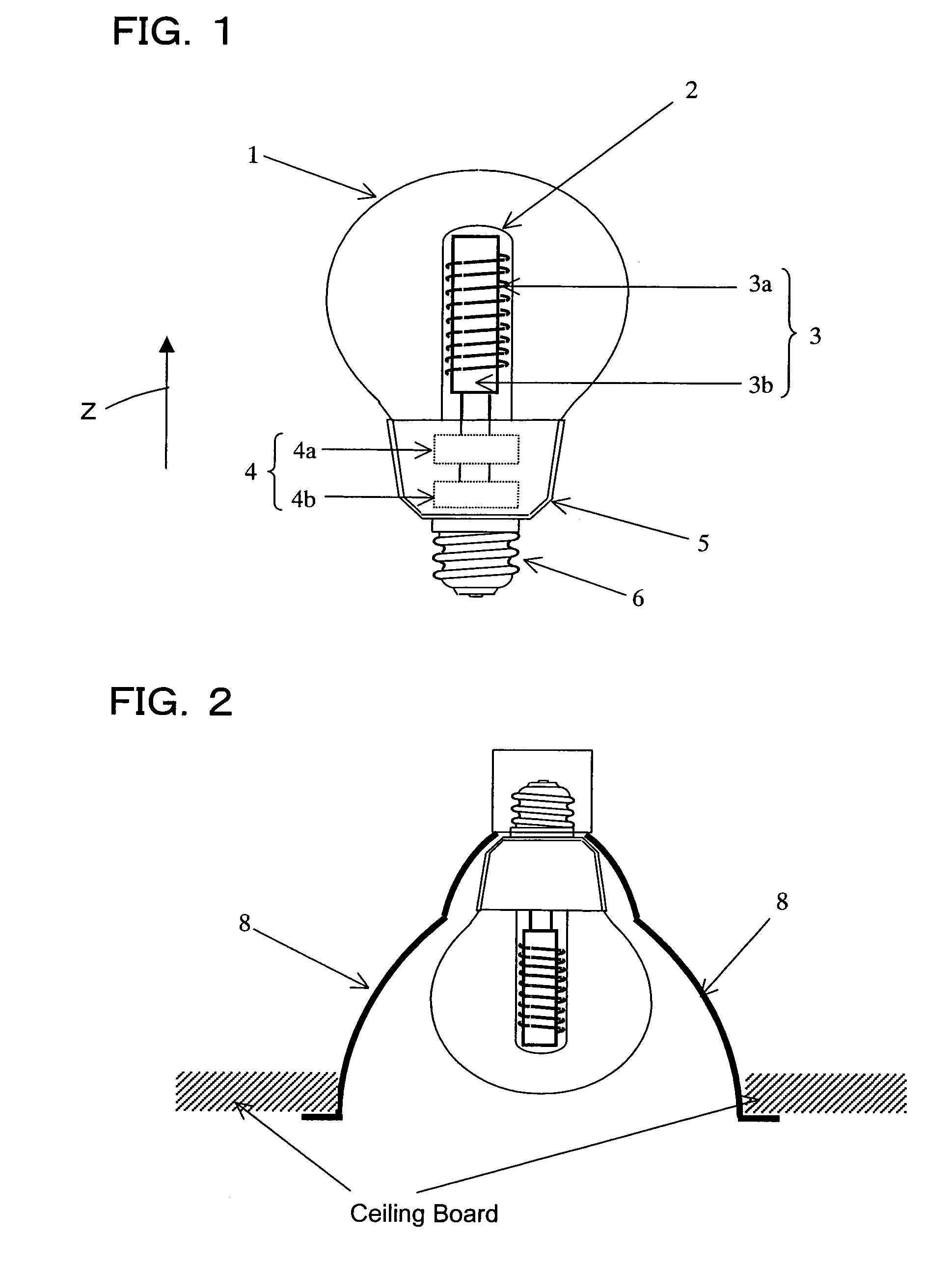
[0040]First, a reference will be made to FIG. 1. FIG. 1 shows a configuration of an electrodeless discharge lamp according to the present embodiment. The lamp according to the present embodiment includes a bulb (envelope) 1 made of a translucent substance such as soda glass. A substance for electric discharge is sealed within the bulb 1. In the present specification, a substance for electric discharge refers to a substance that produces radiation at a given wavelength as a result of electric discharge. While being typically a mixture of various gases, electric discharge substance may contain a substance in liquid phase at normal temperature as long as it transforms into a gaseous phase during lamp operation. While a preferred example of electric discharge substance sealed within the bulb 1 is a mixture of mercury and rare gas (e....


PUM


Abstract

An electrodeless discharge lamp is disclosed that comprises a bulb with a substance for electric discharge sealed therein, the bulb having a reentrant portion protruding inwardly along a Z-axis direction; an induction coil arranged in the reentrant portion, the induction coil having a magnetic core and a winding wound around the magnetic core; and a drive circuit for supplying the induction coil with a power from 50 kHz to 1 MHz. The bulb has an outer diameter from 65 mm to 75 mm in a direction orthogonal to the Z-axis direction, and the magnetic core has a length L in the Z-axis direction that is 1.05 times or more a length L′ of the winding in the Z-axis direction, the length L being set to 41 mm or less.

Description

BACKGROUND OF THE INVENTION[0001]1. Field of the Invention[0002]The present invention relates to an electrodeless discharge lamp that emits light under an electromagnetic field generated by an induction coil arranged in a reentrant portion of a bulb.[0003]2. Description of the Related Art[0004]Recent years have seen a widespread use of fluorescent lamps with higher efficiency and longer life than electric bulb from the viewpoint of global environmental protection. Further, in addition to conventional fluorescent lamps comprising electrodes, electrodeless lamps are under research. Having no electrodes—a factor restricting the life of conventional lamps with electrodes, electrodeless lamp has the advantage that its life is several times longer than that of lamps with electrode, thus holding promise for future widespread use.[0005]Such an electrodeless lamp produces a discharge plasma with a high-frequency electromagnetic field generated by an induction coil arranged in a reentrant por...

Claims


Application Information

Patent Timeline
Patent Type & Authority Patents(United States)
IPC IPC(8): H01J63/04H01J5/50H01J65/04H05B41/24
CPCH05B41/24
Inventor KURACHI, TOSHIAKIKOMINAMI, SATOSHIHASHIMOTODANI, KIYOSHI
Owner PANASONIC CORP
Learn More