
Cuff of wrist-mount blood pressure monitor

Inactive Publication Date: 2006-08-01
OMRON HEALTHCARE CO LTD
View PDF15 Cites 13 Cited by
  • Summary
  • Abstract
  • Description
  • Claims
  • Application Information

AI Technical Summary

Benefits of technology

[0011]The present invention is devised in order to solve the above problems, and its object is to provide a cuff of a wrist-mount blood pressure monitor which adopts a fixing member for making an inflating direction of an inflatable bag to face a wrist so as to enable an air pump to be miniaturized and blood pressure measuring accuracy to be improved.
[0012]A cuff of a wrist-mount blood pressure monitor according to the present invention includes: an inflatable bag to which a predetermined quantity of fluid is supplied in order to press artery of a wrist; and a fixing member for mounting the inflatable bag on the wrist, wherein the fixing member includes: a substantially ring-shaped fixing tool having an opening end including a predetermined gap area, holding the inflatable bag on an inner side of the opening end, and having rigidity for preventing elastic deformation in a state where the inflatable bag is inflated; and a damper for clamping the fixing tool on the wrist in a state where the fixing tool is mounted on the wrist.
[0013]With this structure, even in the state where the inflatable bag is inflated, the fixing tool is not elastically deformed, so that the most part of pressing force caused by the expansion of the inflatable bag contributes to pressure for pressing artery of the wrist. As a result, since a capacity of the inflatable bag is miniaturized, a necessary air flow rate can be reduced, so that the miniaturization of an air pump can be realized. Reduction in an expansion quantity of the inflatable bag suppresses tension generated in the inflatable bag to be small, so that accurate blood pressure measurement can be realized.
[0014]In the cuff of a wrist-mount blood pressure monitor, an inner surface of the fixing tool preferably has a dent portion for preventing contact with a processus styloideus ulnae. The dent portion includes a recess which is provided on an area corresponding to the contact portion with the processus styloideus ulnae, a through hole (opening area), and a portion such as the recess or the through hole filled with a soft material such as sponge. Since the fixing tool of the present invention is not elastically deformed, when the fixing tool is mounted on the wrist, the fixing tool comes in contact with the processus styloideus ulnae, and thus it is considered that the processus styloideus ulnae aches. The dent portion for avoiding the contact with the processus styloideus ulnae is, therefore, provided, so that the fixing tool is avoided contacting with the processus styloideus ulnae, and the cuff of the wrist-mount blood pressure monitor can be mounted on the wrist comfortably. The processus styloideus ulnae is fitted into the dent portion, so that locating of the cuff of the wrist-mount blood pressure monitor with respect to the wrist can be realized.

Problems solved by technology

In the prior cuff of the wrist-mount blood pressure monitor having the above structure, however, since the fixing member is composed of a member with elasticity from a viewpoint of facilitation or the like of the mounting on the wrist, there arises a problem that the fixing member stretches and is deformed according to expansion of the inflatable bag.
Although a tension is generated in the inflatable bag 51 according to its expansion, as the inflatable bag 51 inflates more largely, the tension to be generated becomes stronger, thus deteriorating efficiency of pressure transmission to a blood vessel wall to be pressed.
A phenomenon such that the pressure to be transmitted to the blood vessel wall to be pressed (blood pressure of blood vessel inner wall to be pressed) is stronger than internal pressure in the air bag, therefore, occurs, and thus there also arises a problem that the blood pressure cannot be measured properly.
Since they, however, use an elastic member as a material or a fastening method, the above-mentioned problems arise.

Method used


Image

  • Cuff of wrist-mount blood pressure monitor
  • Cuff of wrist-mount blood pressure monitor
  • Cuff of wrist-mount blood pressure monitor

Examples


first embodiment

(Structure of the Cuff of the Wrist-Mount Blood Pressure Monitor 10)

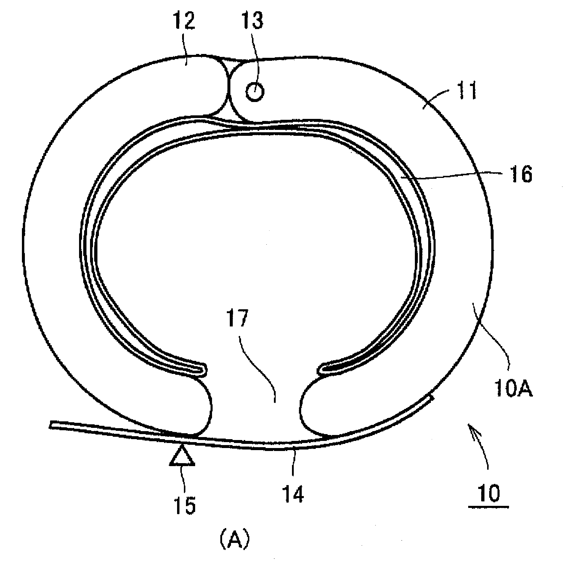
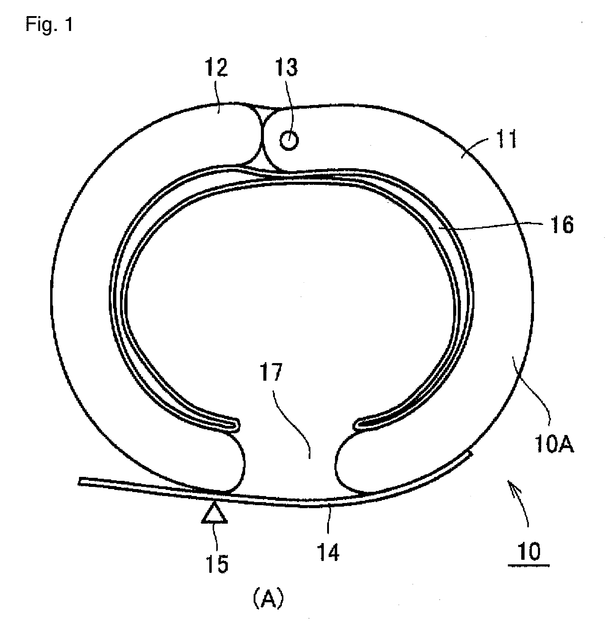
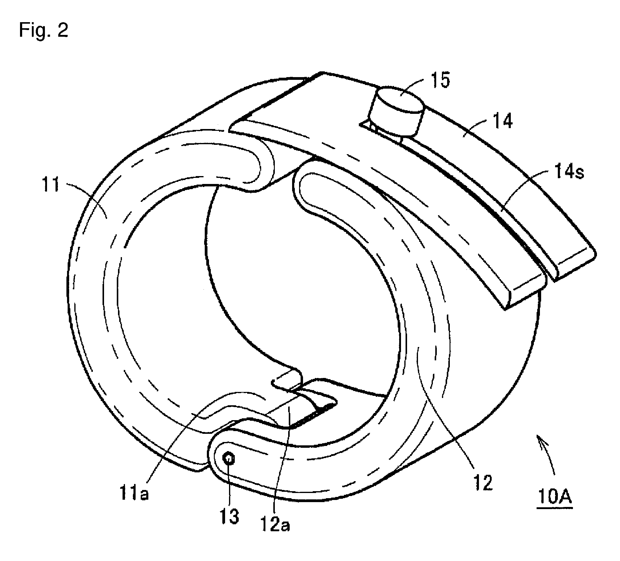
[0026]A structure of the cuff of the wrist-mount blood pressure monitor 10 according to the embodiment of the present invention is explained with reference to FIGS. 1 and 2. FIG. 1 is a sectional view showing the structure of the cuff of the wrist-mount blood pressure monitor 10, and FIG. 2 is a whole perspective view showing only a structure of a fixing member 10A of the cuff of the wrist-mount blood pressure monitor 10.

[0027]With reference to these drawings, the cuff of the wrist-mount blood pressure monitor 10 has an inflatable bag 16 to which a predetermined quantity of fluid is supplied in order to press predetermined artery of a wrist, and the fixing member 10A for mounting the inflatable bag 16 on the wrist. The fixing member 10A has a first half split ring-shaped fixing tool 11 and a second half split ring-shaped fixing tool 12 having an approximately ring shape which are not elastically deformed in a state ...

second embodiment

[0035]Since the characteristics of the cuff of the wrist-mount blood pressure monitor in this embodiment is the structure of the fixing member, only the structure of the fixing member will be explained. The other parts of the structure are the same as the structure of the cuff of the wrist-mount blood pressure monitor 10 in the first embodiment. The structure of the fixing member 10B is explained with reference to FIG. 4. FIG. 4 is a whole perspective view showing the structure of the fixing member 10B.

(Structure of the Fixing Member 10B)

[0036]When the fixing member 10B in this embodiment is compared with the structure of the fixing member 10A in the first embodiment, a predetermined area of the first half split ring-shaped fixing tool 11 has an opening area 11h for avoiding contact with a processus styloideus ulnae of the wrist. The other parts of the structure are the same as the structure of the fixing member 10A.

(Working Effect)

[0037]The cuff of the wrist-mount blood pressure mo...

third embodiment

[0040]Since the characteristic of the cuff of the wrist-mount blood pressure monitor in this embodiment is the structure of the fixing member, only the structure of the fixing member will be explained. The other parts of the structure are the same as the structure of the cuff of the wrist-mount blood pressure monitor 10 in the first embodiment. The structure of the fixing member 10C will be explained below with reference to FIG. 5. FIG. 5 is a whole perspective view showing the structure of the fixing member 10C.

(Structure of the Fixing Member 10C)

[0041]When the fixing member 10C in this embodiment is compared with the structure of the fixing member 10A in the first embodiment, the connected position of the first half split ring-shaped fixing tool 11 and the second half split ring-shaped fixing tool 12 by means of the hinge 13 shifts from an axial center C. The other parts of the structure are the same as the structure of the fixing member 10A.

(Working Effect)

[0042]Also the cuff of ...


PUM


Abstract

A cuff of a wrist-mount blood pressure monitor includes an inflatable bag to which a predetermined quantity of fluid is supplied in order to press predetermined artery of a wrist, and a fixing member for mounting the inflatable bag on the wrist. The fixing member has a first half split ring-shaped fixing tool and a second half split ring-shaped fixing tool having an approximately ring shape with rigidity for preventing elastic deformation in a state where the inflatable bag is inflated.

Description

BACKGROUND OF THE INVENTION[0001]1. Field of the Invention[0002]The present invention relates to a cuff of a wrist-mount blood pressure monitor which is used in a blood pressure monitor which is mounted on the body of a subject so as to measure blood pressure and, more particularly, to a structure of the cuff of a wrist-mount blood pressure monitor used in a wrist-mount blood pressure monitor for monitoring the blood pressure on the wrist.[0003]2. Description of the Related Art[0004]In general, the cuff of the wrist-mount blood pressure monitor to be used in a wrist-mount blood pressure monitor is composed of an inflatable bag into which a fluid such as air is supplied, and a fixing member to be mounted on a portion of a subject. After the inflatable bag is mounted on the wrist by using the fixing member, gas such as air is supplied to the inflatable bag, so that the artery of the subject is pressed and blood pressure is measured at a pressuring process or an exhaust process of the ...

Claims


Application Information

Patent Timeline
IPC IPC(8): A61B5/05A61B5/022
CPCA61B5/681A61B5/02233
Inventor YAMAKOSHI, KEN-ICHIINOUE, TOMONORITANAKA, TAKAHIDESANO, YOSHIHIKOOKU, SHOJIRO
Owner OMRON HEALTHCARE CO LTD
Learn More