
Magnetostrictive stress wave sensor

a stress wave sensor and magnetic field technology, applied in the field of shock sensors, can solve the problems of reducing the value of vehicles, so as to achieve the effect of large voltage output and easy detection and digitization

Active Publication Date: 2006-07-25
LITTELFUSE INC
View PDF11 Cites 2 Cited by
  • Summary
  • Abstract
  • Description
  • Claims
  • Application Information

AI Technical Summary

Benefits of technology

The solution enables early and accurate detection of crash severity, particularly in non-ferrous structural elements, reducing unnecessary safety system deployments and associated costs while maintaining effectiveness in severe crashes.

Problems solved by technology

At the same time, considerable cost can be saved if safety systems are not deployed in less severe crashes where passive restraints such a seat belts are likely to be sufficient to prevent serious injury.
As automobiles employ larger numbers of air bags and other deployable safety systems, the cost of replacing deployed safety systems becomes a considerable portion of the cost of repairs following a crash.
Of course, in a severe crash, when deployment of all safety systems is desired, the automobile may have little residual value due to the extensive damage caused by the crash.

Method used


Image

  • Magnetostrictive stress wave sensor
  • Magnetostrictive stress wave sensor
  • Magnetostrictive stress wave sensor

Examples


Embodiment Construction

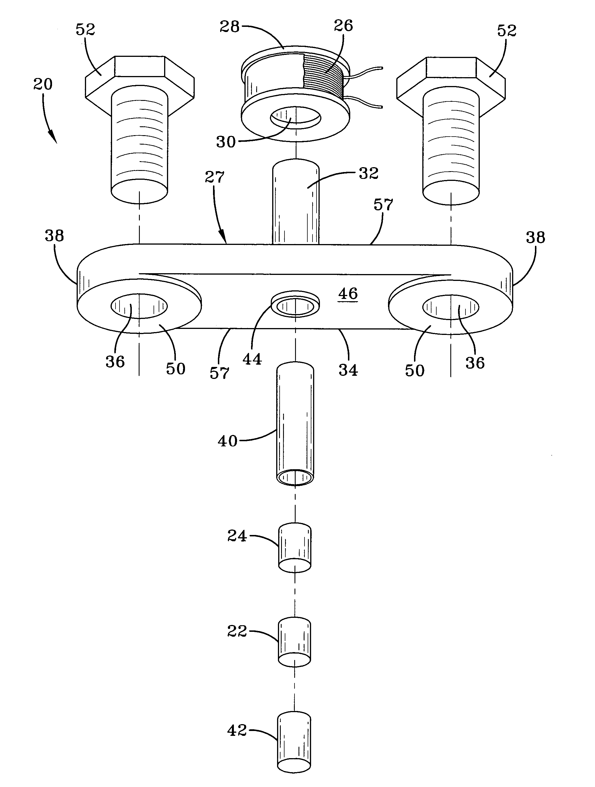
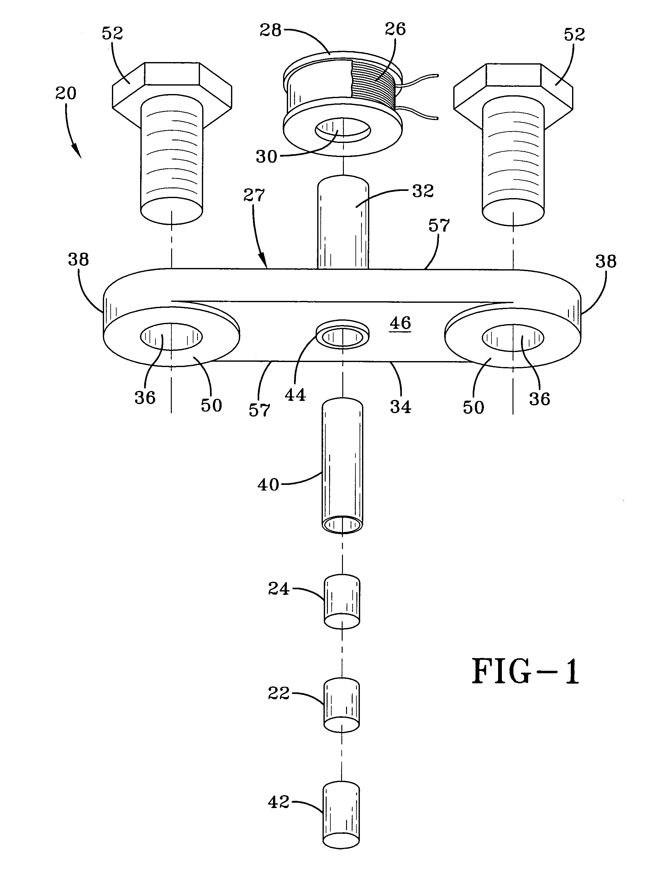
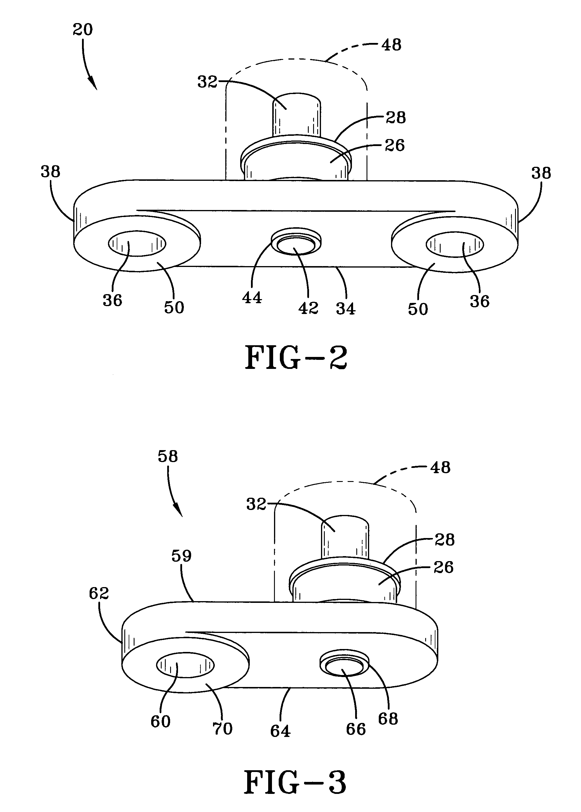
[0014]Referring to FIGS. 1–4, wherein like numbers refer to similar parts, a crash sensor 20 is shown in FIG. 2. The crash sensor 20, as shown in FIG. 1, has three functional elements: a Terfenol-D (Tb0.3 Dy0.7 Fe1.92) sensing element 22, a biasing magnet 24, and a sensing coil 26 mounted on a housing 27. The housing 27 has a cylindrical portion 32 that projects from a beam 34. The shock sensor 20 incorporates a bobbin 28 on which the sensing coil 26 is wound. The bobbin 28 has a central aperture 30 that fits over the cylindrical housing portion 32. The sensing coil 26 can have for example, around 1,000 turns of thirty-six gauge wire. The beam 34 extends on either side of the cylindrical housing portion 32 and has two apertures 36, one formed in each end 38 of the beam. As shown in FIG. 1, a sleeve 40 is loaded with a cylindrical biasing magnet 24, a cylindrical Terfenol-D sensing element 22 and a cylindrical spacing element 42 that protrudes from the sleeve 40. The biasing magnet 2...


PUM

PropertyMeasurementUnit
giant magnetostrictiveaaaaaaaaaa
magnetic fieldaaaaaaaaaa
strengthaaaaaaaaaa

Abstract

A shock sensor has a housing with a Terfenol-D type sensing element positioned inside a sensing coil. A permanent biasing magnet is positioned in engagement with the Terfenol-D sensing element, and a spacer engages the Terfenol-D sensing element and extends from the housing. The housing has a beam with one or two mounting holes through which fasteners extend to mount the shock sensor to a structural member. The housing places the spacer in compression against the structural member. In an alternative embodiment a DC current can be supplied to the sensing coil to provide the biasing magnetic field. A high frequency filter separates the shock sensing signal from the applied DC biasing current.

Description

FIELD OF THE INVENTION[0001]The present invention relates to shock sensors for monitoring vehicle crashes in general, and to shock sensors utilizing the magnetostrictive effect in particular.BACKGROUND OF THE INVENTION[0002]The modern automobile is equipped with many active safety systems, from seat belt tensioners, to air bags and fuel cutoff valves. To properly trigger the activation of the various active safety systems, crash sensors are used to detect the onset of a crash and to determine the severity of a crash. To optimize the use of active safety systems it is important to know as soon as possible the likely severity of the crash. Better results can be achieved by early detection of crash severity and early deployment of active safety systems. At the same time, considerable cost can be saved if safety systems are not deployed in less severe crashes where passive restraints such a seat belts are likely to be sufficient to prevent serious injury. As automobiles employ larger nu...

Claims


Application Information

Patent Timeline
Patent Type & Authority Patents(United States)
IPC IPC(8): H01F7/00G01H1/00G01H11/04G01N29/00G01P15/08
CPCB60R21/0136G01P15/0891G01P15/0885G01H11/04G01P3/12G01P1/02
Inventor STUVE, STEVEN R.
Owner LITTELFUSE INC
Learn More