
Bristle brush for concrete sanding

a concrete sanding and bristle technology, applied in the field of reinforced bristles, can solve the problems of inability to withstand constant scuffing, dilemma of cleaning, and inherently produce dust on the concrete floor, and achieve the effect of retaining the flexibility of the metal substra

Active Publication Date: 2006-07-25
DIAMABRUSH
View PDF22 Cites 20 Cited by
  • Summary
  • Abstract
  • Description
  • Claims
  • Application Information

AI Technical Summary

Benefits of technology

The solution maintains high sanding performance throughout the bristle's life, efficiently prepares both high and low spots on concrete surfaces, and reduces dust and heat-related issues, enabling faster and more even surface preparation.

Problems solved by technology

While concrete or cement is a very popular material for use in floors and construction materials because of its strength, durability and low costs, if the concrete or cement is left unfinished, the concrete floor will inherently produce dust by the constant scuffing it undergoes whether by foot traffic or wheeled traffic and be susceptible to staining due to porosity.
One is thus faced with a dilemma of cleaning a concrete floor with its no gloss utilitarian appearance and with the disadvantage of the inevitable dust that emanates from an unfinished concrete floor or spending considerable money for a protective and decorative covering surface.
Part of the expense to obtain a decorative and protective covering is due to the preparation of the concrete floor to accept a covering surface.
Aggressive sanding of the concrete surface is a time consuming effort requiring frequent replacement of the sand paper as the sand particles become worn.
While these pads performed well when new, the particle edges become rounded out through wear and the sanding performance substantially diminishes.
Other problems are known that also prevent or limit the application of hardened particles.
The generated heat is sufficient to melt the plastic material and fuses the bristles together rendering the bristle pad useless.
Previous metal bristles, if fully brazed with particles become too brittle and break off during high speed application.
Pads or wide sanding surfaces encounter problems with wavy or uneven concrete surfaces.
They have a tendency to miss the low spots.
As a result, to reach the low spots, they must remove the high spots which results in extra sanding and effort.

Method used


Image

  • Bristle brush for concrete sanding
  • Bristle brush for concrete sanding
  • Bristle brush for concrete sanding

Examples


Embodiment Construction

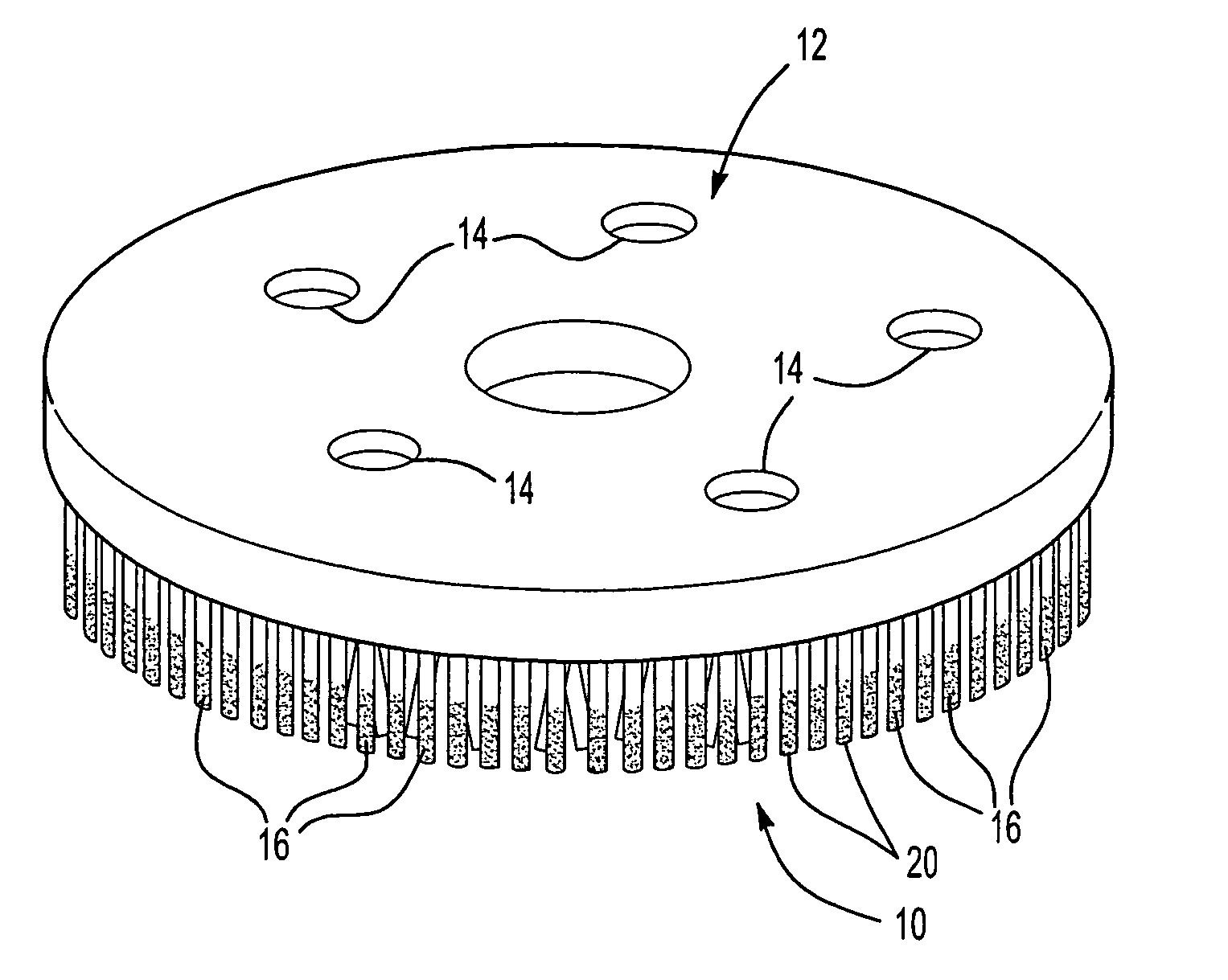
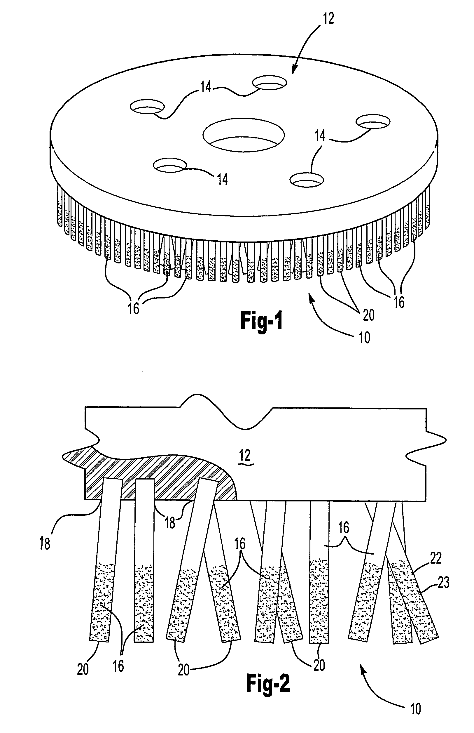
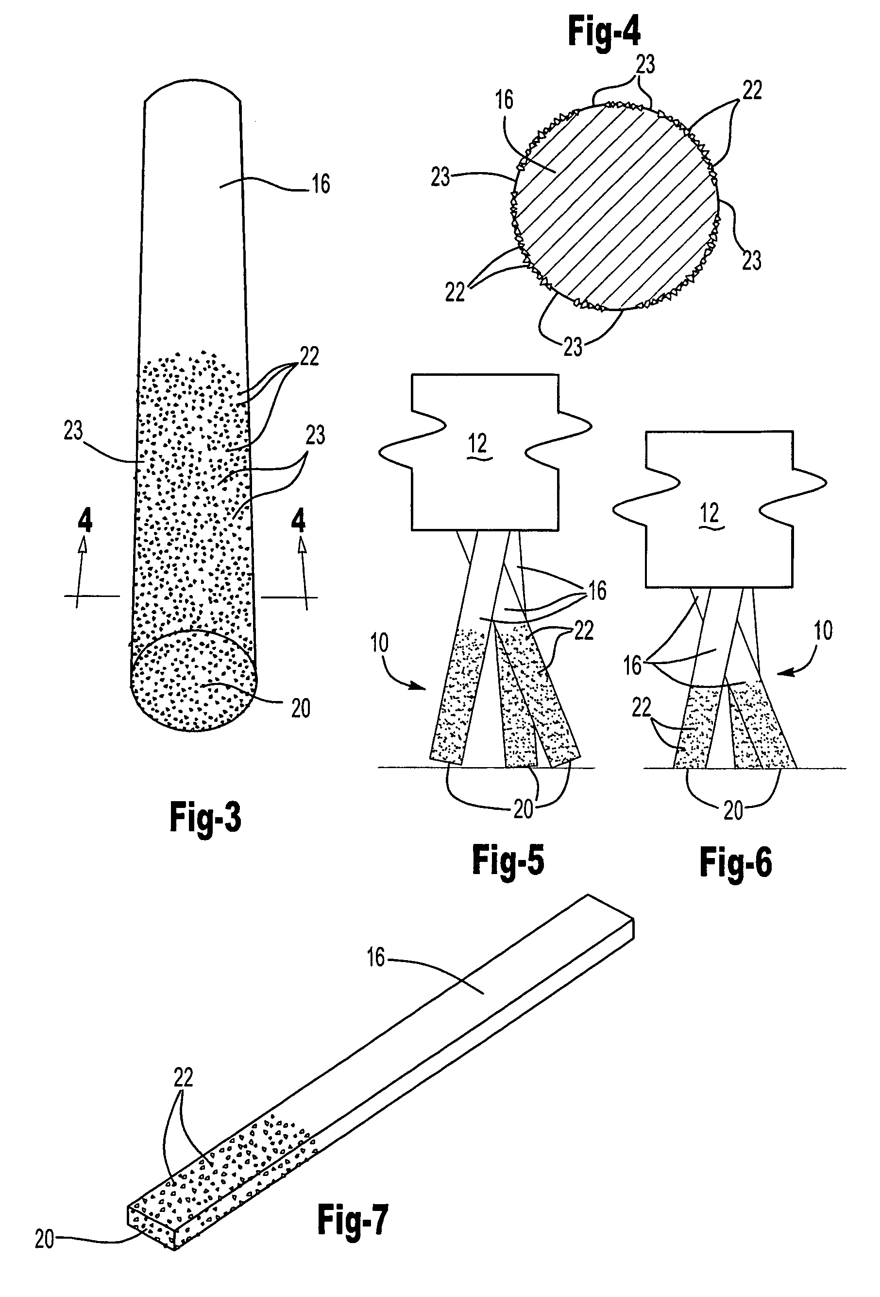
[0022]Referring now to FIG. 1, an abrasive brush 10 for use on a conventional high speed power sanding machine (not shown), has a base 12 that has conventional quick connect fittings 14 in the form of apertures which removably snap fit onto conventional studs (not shown) on the sander. The base which can be made from a plastic material mounts a proximate end 18 of a plurality of bristles 16 extending from the base 12. The bristles 16 may be arranged in a generally vertical direction as shown in FIG. 1. Preferably as clearly shown in FIGS. 2, 5–6, the bristles extend downwardly at differing angles. Whatever the angle, each bristle preferably has its distal end 20 generally or nearly coplanar with the other distal ends as more clearly shown in FIG. 2.

[0023]Reference now is made to FIG. 3 and 4 where the bristle 16 is shown to have a plurality of diamond particles 22 brazed or otherwise secured onto the surface of the bristle from its distal end and extending at least halfway up the di...


PUM


Abstract

A brush or pad (10) for a power sander for sanding surfaces includes a base (12) for mounting onto a power sander and a plurality of depending bristles (16) with the bristles having a plurality of hard particles (22), for example diamonds particles of grit 70 size, brazed or otherwise secured onto the bristle surface such that as the bristle wears down, new particle surfaces are exposed at the distal end (20) of the bristle to maintain sanding performance of the brush. The particles (22) may be spot brazed in steel with a brazing alloy to retain flexibility of the steel bristle.

Description

[0001]This Application is a Continuation-In-Part of pending U.S. Ser. No. 10 / 851,393 filed on May 21, 2004.TECHNICAL FIELD[0002]The field of this invention relates to a reinforced brush for sanding concrete floors and surfaces.BACKGROUND OF THE DISCLOSURE[0003]While concrete or cement is a very popular material for use in floors and construction materials because of its strength, durability and low costs, if the concrete or cement is left unfinished, the concrete floor will inherently produce dust by the constant scuffing it undergoes whether by foot traffic or wheeled traffic and be susceptible to staining due to porosity.[0004]One is thus faced with a dilemma of cleaning a concrete floor with its no gloss utilitarian appearance and with the disadvantage of the inevitable dust that emanates from an unfinished concrete floor or spending considerable money for a protective and decorative covering surface. Part of the expense to obtain a decorative and protective covering is due to th...

Claims


Application Information

Patent Timeline
Patent Type & Authority Patents(United States)
IPC IPC(8): B24D17/00A46B13/00A46D1/00B24B7/18B24B23/03B24B41/04B24D13/14B24D13/16B24D99/00
CPCA46B13/008A46B13/02B24D13/16B24B7/186B24B23/03B24B41/042B24D13/145A46D1/0207A46B2200/3093A46D1/00
Inventor PALUSHAJ, SIMON
Owner DIAMABRUSH
Learn More