
Mounting structure of a vehicle interior part

a technology for interior parts and mounting structures, which is applied to roofs, screws, threaded fasteners, etc., can solve the problems of affecting the smooth mounting of the interior part to the vehicle body, affecting the stability of the interior part, etc., and achieves the effect of sufficient strength

Inactive Publication Date: 2006-07-18
TOYOTA JIDOSHA KK
View PDF14 Cites 37 Cited by
  • Summary
  • Abstract
  • Description
  • Claims
  • Application Information

AI Technical Summary

Benefits of technology

The patent describes a mounting structure for interior parts of a vehicle that includes a first engaging portion, a second engaging portion, and a movement limiting portion. The first engaging portion is attached to the vehicle body, the second engaging portion is attached to the interior part, and the movement limiting portion is stored in the interior part. The movement limiting portion limits the movement of the interior part away from the vehicle body by a predetermined distance when the second engaging portion is disengaged. The movement limiting portion includes an end that serves as an anchor portion and a flexible portion that connects the anchor portion and the second engaging portion. The mounting structure is designed to securely mount the interior part to the vehicle body and prevent it from moving away from the vehicle body.

Problems solved by technology

In the conventional mounting structure as described above, at the time of or after mounting the interior part to the vehicle body, the strap that connects the vehicle body-side engaging portion and the interior part-side engaging portion may interfere with mounting the interior part to the vehicle body smoothly.
Besides, a portion between the vehicle body-side engaging portion and the strap or between the interior part-side engaging portion and the strap may be twisted and broken when the interior part is detached away from the vehicle body.

Method used


Image

  • Mounting structure of a vehicle interior part
  • Mounting structure of a vehicle interior part
  • Mounting structure of a vehicle interior part

Examples


Embodiment Construction

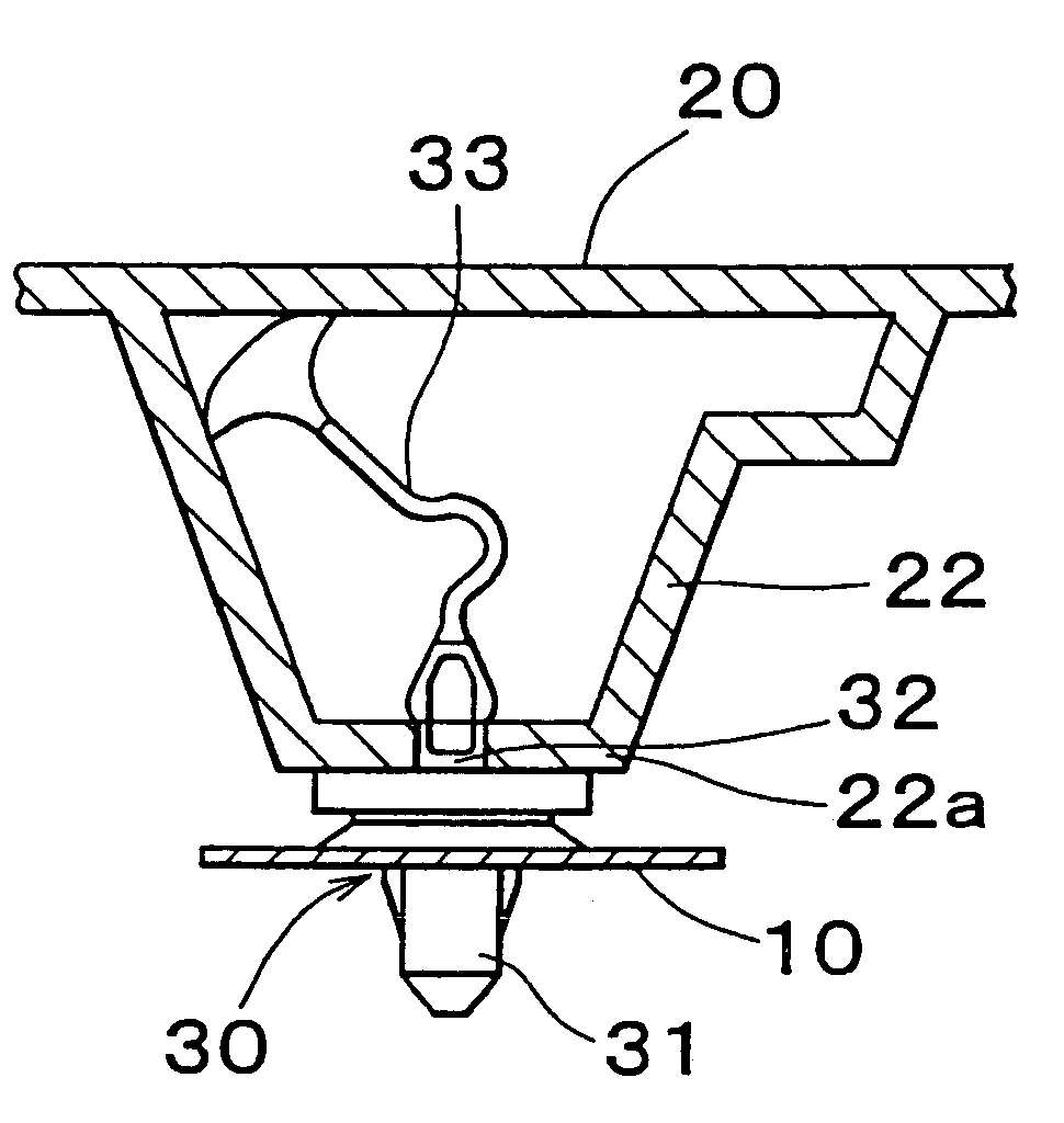
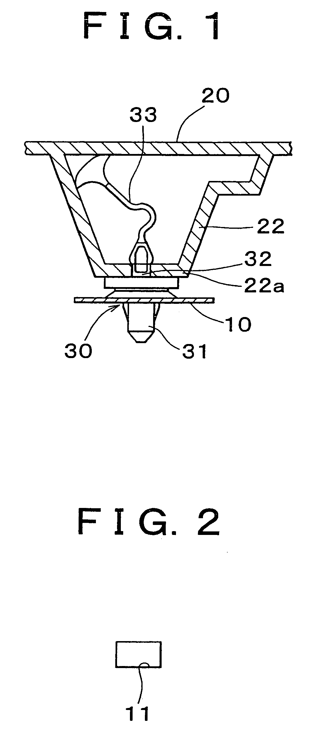
[0025]Hereinafter, an embodiment of the invention will be described with reference to the accompanying drawings. FIG. 1 shows a pillar garnish 20 as a vehicle interior part which is mounted onto a pillar 10 of a vehicle body using a mounting device 30. A rectangular mounting hole 11 shown in FIG. 2 is formed in the pillar 10 while a trapezoidal interior space 22 including a rectangular mounting hole 21 shown in FIG. 3 formed in the lower end is formed in the pillar garnish 20.

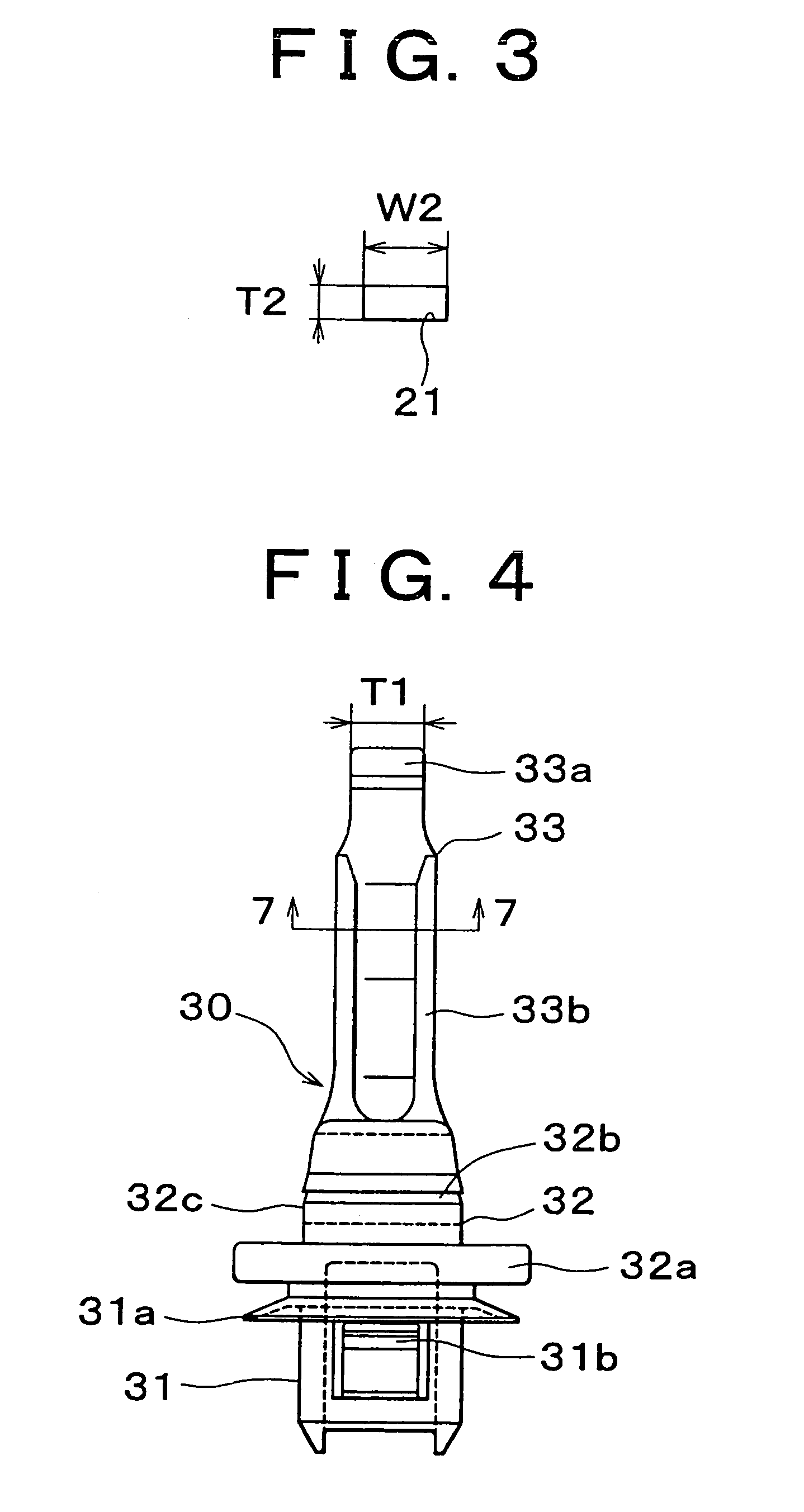
[0026]As shown in FIGS. 4 to 10, the mounting device 30 includes a first engaging portion 31 at one end thereof (lower end portion shown in FIG. 4), a second engaging portion 32 at an intermediate portion thereof, and a movement limiting portion 33 at the other end thereof, which are integrally formed of a synthetic resin material (e.g. fiber reinforced nylon). The first engaging portion 31 includes a hood-like portion 31a and a pair of engaging claws 31b. The hood-like portion 31a is adapted to elastically abu...


PUM


Abstract

A mounting device (30) for mounting a vehicle interior part (20) to a vehicle body 10 includes a first engaging portion (31), a second engaging portion (32), and a movement limiting portion (33). The first engaging portion (31) is engaged and thus fixed to the vehicle body (10) so as to be kept from being disengaged therefrom under a predetermined load. The second engaging portion (32) is engaged and thus fixed to the interior part (20) so as to be disengaged therefrom under the predetermined load. While the second engaging portion (32) is engaged with the interior part (20), the movement limiting portion (33) is kept within an interior space (22) formed in the interior part (20). When the interior part is detached and moves away from the vehicle body (10), the movement limiting portion (33) prevents the interior part (20) from moving away from the vehicle body (10) by a distance exceeding a predetermined value.

Description

BACKGROUND OF THE INVENTION[0001]1. Field of Invention[0002]The invention relates to a mounting structure of a vehicle interior part in which the vehicle interior part is mounted to a vehicle body using a fixing device.[0003]2. Description of Related Art[0004]A mounting structure of a vehicle interior part is disclosed in WO99 / 67542. In this mounting structure, an interior part is mounted onto a vehicle body with a fixing device (a clip) having a portion engaged with the vehicle body (vehicle body-side engaging portion), a portion engaged with the interior part (an interior part-side engaging portion), and a flexible strap that connects the vehicle body-side engaging portion and the interior part-side engaging portion. The force generated by the engagement of the interior part-side engaging portion with a protrusion formed in the vehicle body side engaging portion, that is, pulling resistance, is set to be smaller than the force generated by the engagement of the vehicle body-side e...

Claims


Application Information

Patent Timeline
Patent Type & Authority Patents(United States)
IPC IPC(8): B62D25/04B60R13/02F16B5/06F16B5/12F16B19/00
CPCB60R13/0206F16B5/0657F16B5/065B60R13/02
Inventor TOKUNAGA, SHINYA
Owner TOYOTA JIDOSHA KK
Learn More