Vector monitor, related method of controlling a transmitter and transmitter employing the same

a technology of vector monitor and transmitter, which is applied in the field of communication systems, can solve the problems of difficult effective implementation, high cost, and difficulty in achieving the effect of combining amplitude and phase modulation such as may be found with orthogonal frequency division multiplex (ofdm) signals, and achieves significant phase and amplitude distortion of the delivery of improved spectral efficiency of transmitted signals in linear modulation schemes

Inactive Publication Date: 2006-07-11
AVAGO TECH WIRELESS IP SINGAPORE PTE
View PDF9 Cites 13 Cited by
  • Summary
  • Abstract
  • Description
  • Claims
  • Application Information

AI Technical Summary

Benefits of technology

[0007]To address the above-discussed deficiencies of the prior art, the present invention is directed to a vector monitor for use with a transmitter employing in-phase and quadrature phase input and feedback signals. In one embodiment, the vector monitor includes an error detection circuit configured to provide first and second components of an error signal based on the input and feedback signals. Additionally, the vector monitor includes a comparator circuit, coupled to the error detection circuit, configured to compare a resultant vector of the first and second components to a comparison boundary and to control a power level of the transmitter based on the comparison.

Problems solved by technology

While attempting to augment the available bandwidth of channels within a given transmission frequency range (e.g., 2.5 to five gigahertz range), the combined use of amplitude and phase modulation such as may be found with orthogonal frequency division multiplex (OFDM) signals, has proven difficult to effectively implement.
More specifically, the delivery of improved spectral efficiency of transmitted signals in linear modulation schemes typically undergoes significant distortion of both phase and amplitude when the modulated signals are boosted by a power amplifier for transmission to a receiver.
The distortion is especially prevalent in transmitters that employ power efficient, but nonlinear, power amplifiers.
In this type of linearization technique, a Cartesian feedback section is provided after the power amplifier, which would otherwise introduce undesirable distortion into a modulated output signal.
If a required power output level of the power amplifier is too large, however, the power amplifier may limit or clip its output signal thereby introducing a distortion level that Cartesian feedback linearization cannot fully correct.
Unfortunately, the high operational efficiency of the power amplifiers usually necessitates an operational level that approaches the point of limiting or clipping, thereby presenting an important design and operational dilemma.
Additionally, changes in an output load associated with the power amplifier may also cause changes in both loop gain and loop phase, which may lead to feedback loop instability including oscillation.

Method used


Image

  • Vector monitor, related method of controlling a transmitter and transmitter employing the same
  • Vector monitor, related method of controlling a transmitter and transmitter employing the same
  • Vector monitor, related method of controlling a transmitter and transmitter employing the same

Examples


Embodiment Construction

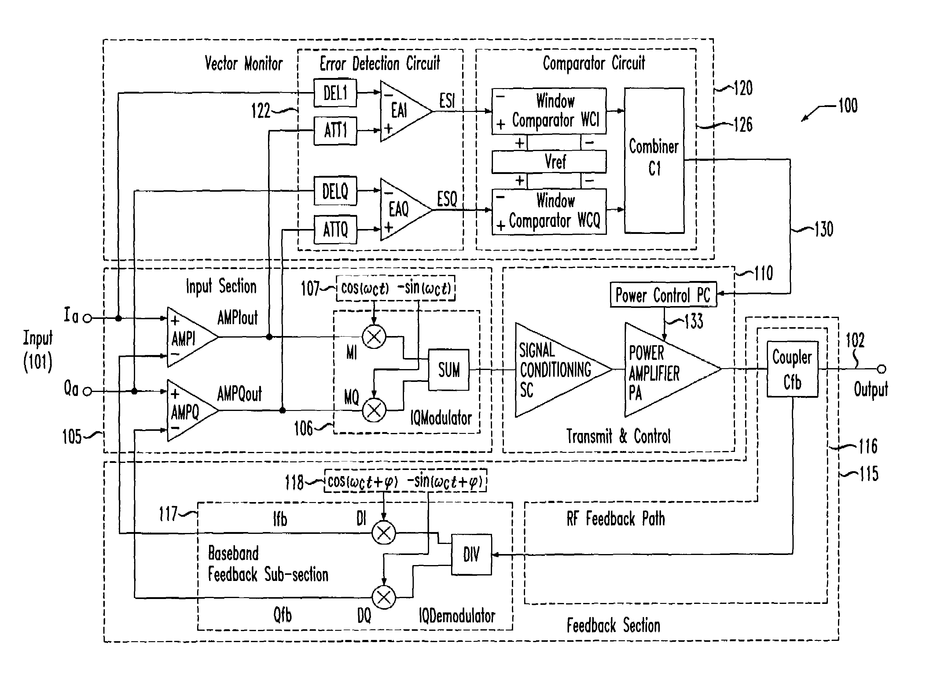
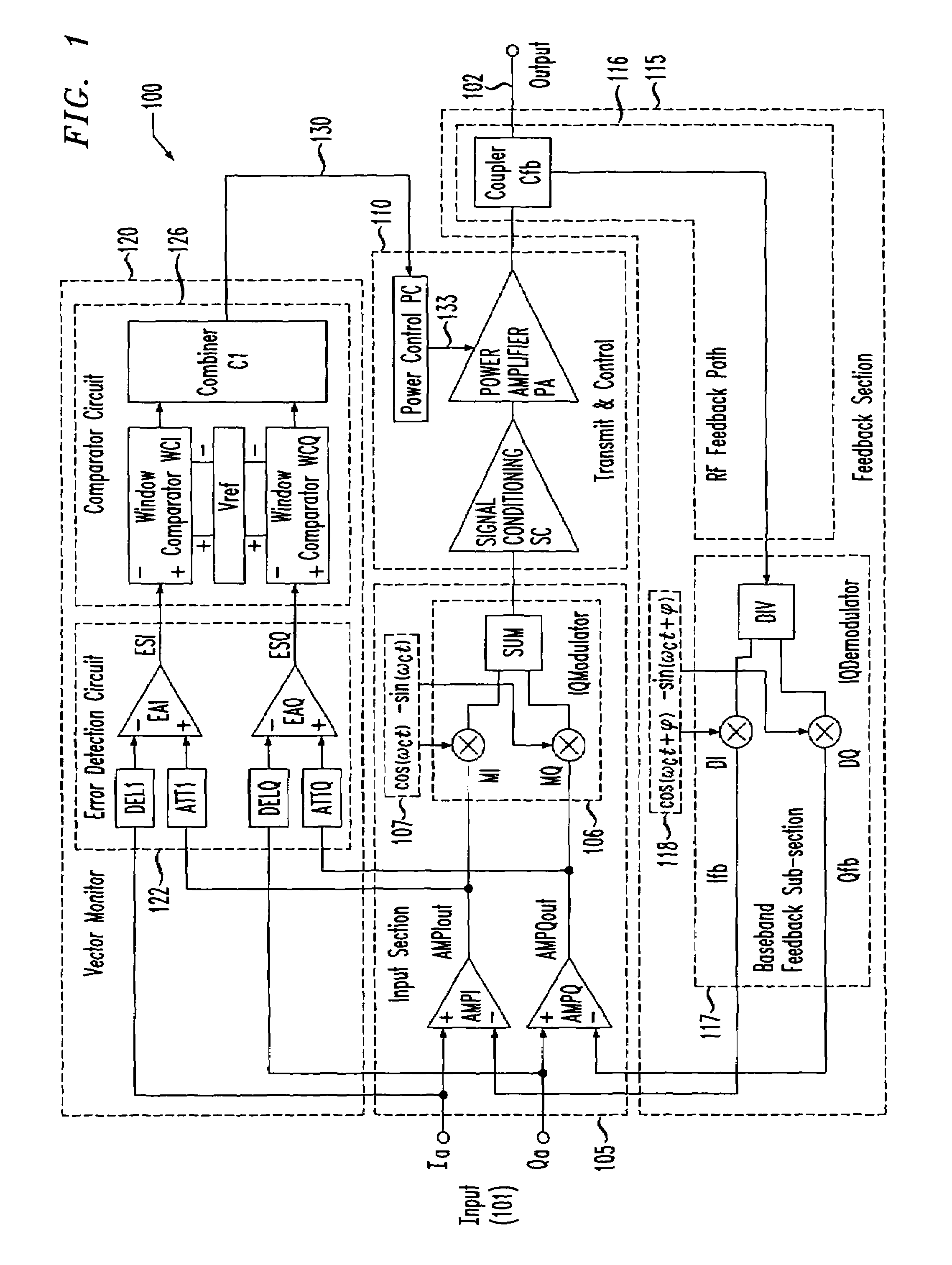
[0020]Referring initially to FIG. 1, illustrated is a system diagram of an embodiment of a transmitter, generally designated 100, employing in-phase and quadrature phase (Cartesian) input and feedback signals (wherein both may be referred to as in-phase and quadrature phase signals) including an embodiment of a vector monitor 120 constructed in accordance with the principles of the present invention. The transmitter 100 includes an input 101 employing in-phase and quadrature phase input signals Ia, Qa, respectively, and an output 102. The transmitter 100 further includes an input section 105 coupled to the input 101, a transmit and control section 110 coupled between the input section 105 and the output 102, and a feedback section 115, coupled between the output 102 and the input 101, having a radio frequency (RF) feedback path 116 and a baseband feedback subsection 117. The transmitter 100 still further includes the vector monitor 120 having an error detection circuit 122 and a com...


PUM

PropertyMeasurementUnit
transmission frequencyaaaaaaaaaa
frequencyaaaaaaaaaa
frequencyaaaaaaaaaa

Abstract

The present invention is directed to a vector monitor for use with a transmitter employing in-phase and quadrature phase input and feedback signals, and a method of controlling a transmitter. In one embodiment, the vector monitor includes an error detection circuit configured to provide first and second components of an error signal based on the input and feedback signals. Additionally, the vector monitor includes a comparator circuit, coupled to the error detection circuit, configured to compare a resultant vector of the first and second components to a comparison boundary and control a power level of the transmitter based on the comparison.

Description

CROSS REFERENCE TO RELATED APPLICATION[0001]This application is related to U.S. patent application Ser. No. 10 / 442,738 entitled “Comparator Circuit, Related Method of Comparing a Vector to Comparison Boundaries and Transmitter Employing the Same,” to Erik B. Busking, filed concurrently herewith, which is commonly assigned with the present invention and incorporated herein by reference as if reproduced herein in its entirety.TECHNICAL FIELD OF THE INVENTION[0002]The present invention is directed, in general, to communication systems and, more specifically, to a vector monitor, a method of controlling a transmitter and a transmitter employing the same.BACKGROUND OF THE INVENTION[0003]As the demand for high-speed telecommunications systems increases, more signal bandwidth is required for use therein. While attempting to augment the available bandwidth of channels within a given transmission frequency range (e.g., 2.5 to five gigahertz range), the combined use of amplitude and phase mod...

Claims


Application Information

Patent Timeline
Patent Type & Authority Patents(United States)
IPC IPC(8): G06F11/00G06K5/04G11B5/00G11B20/20H03C3/40H03F1/06H03F1/32H03F3/24H04L27/34H04L27/36
CPCH03C3/406H03F1/0205H03F1/3247H04L27/364H03F3/24H04L27/34H03F1/3294
Inventor BUSKING, ERIK B.
Owner AVAGO TECH WIRELESS IP SINGAPORE PTE
Why Eureka
Try Eureka