
Variable optical element, a pickup apparatus having the variable optical element, and an information recording and reproducing apparatus having the pickup apparatus

a pickup apparatus and variable technology, applied in the field of variable optical elements, can solve the problems of unstable optical characteristics of the optical system including the above mentioned objective lens, medium but not suitable for the other type of information recording medium, and large-scale mechanism is required

Inactive Publication Date: 2006-07-11
PIONEER CORP
View PDF5 Cites 0 Cited by
  • Summary
  • Abstract
  • Description
  • Claims
  • Application Information

AI Technical Summary

Benefits of technology

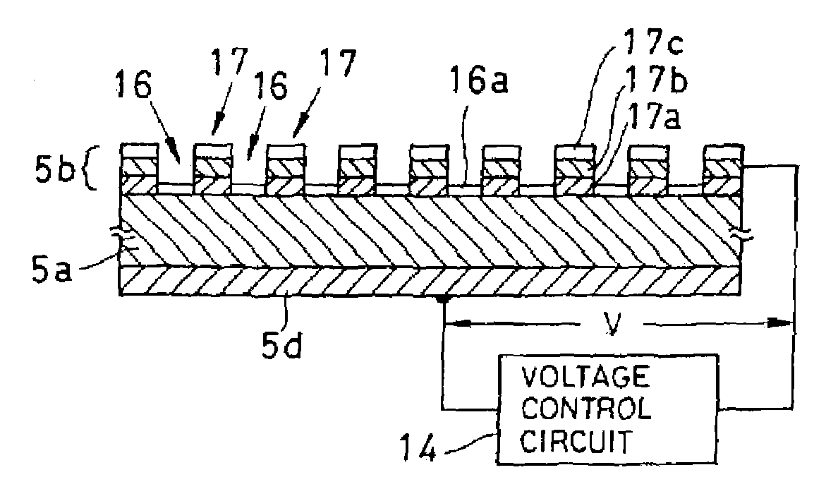
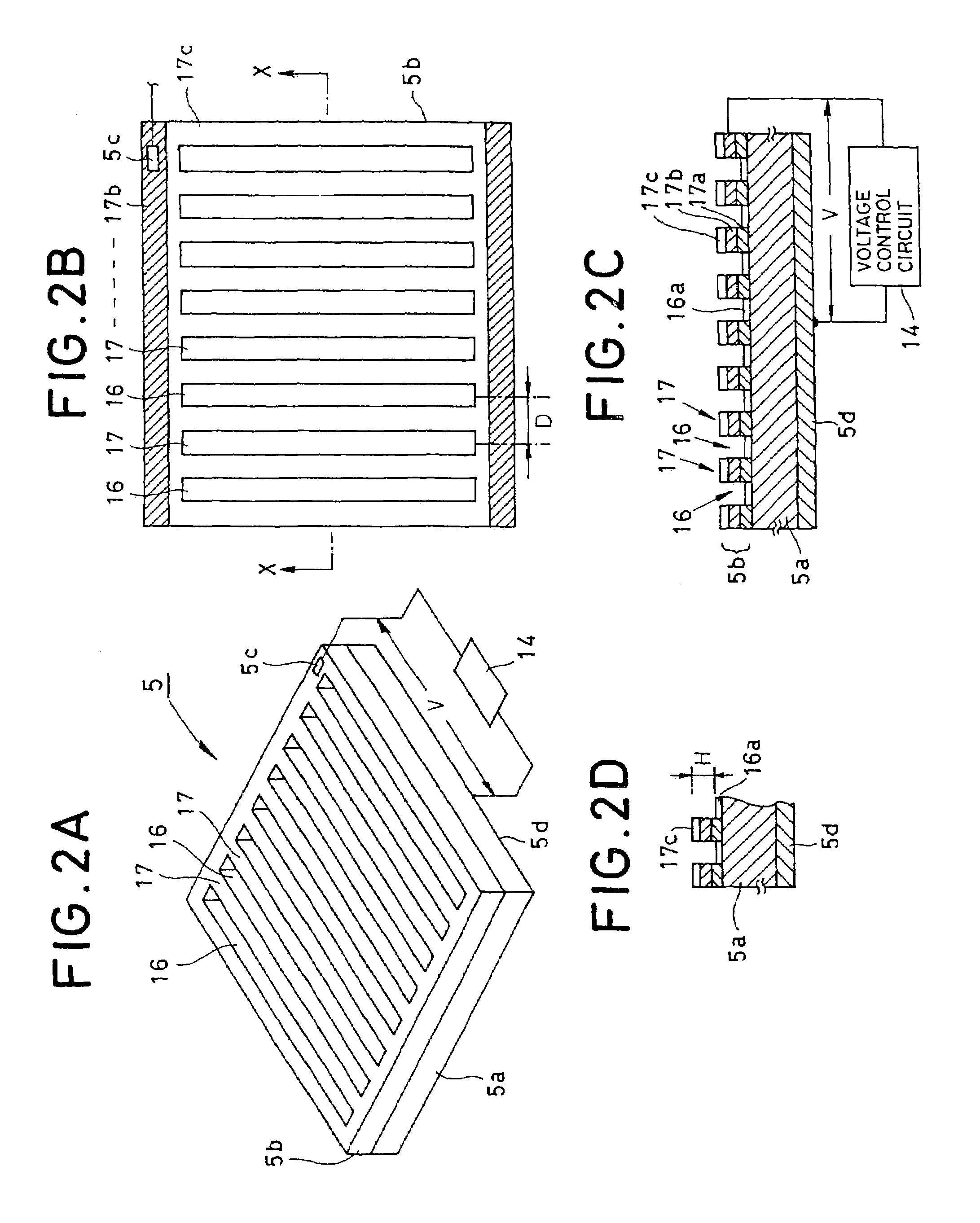
[0021]According to the first or the second aspect of the invention, when a piezo-electric medium layer is distorted by the piezo-electric effect, optical characteristics of the first and the second areas are changed, a variable optical element causes optical changes to the wave front of the light incident on the first and the second areas and reflects it. Thus, by controlling the piezo-electric effect of a piezo-electric layer, various changes can be imparted to the incident light, which, for example, allows such effects as the appropriate control of the optical characteristics of a light beam irradiated onto an information recording medium for the purpose of recording or reproducing information.
[0031]According to the information recording / reproducing apparatus in the seventh or eighth aspect, it is possible to variably control the diffraction efficiency of a variable optical element by adjusting the voltages applied to a piezo-electric medium layer. Based on this, it is possible to eliminate problems where information on an information recording medium is unnecessarily erased by appropriately adjusting the power of the light beam for recording information to or reproducing information from an information recording medium.

Problems solved by technology

However, while above mentioned crosstalk canceling technique is applied to the reproduction of information from a reproduction-only information recording medium such as a DVD-ROM (digital versatile disc read only memory), which proves effective in reproducing information with good accuracy, if it is applied to the reproduction of information recorded on a phase-change type information recording medium such as a DVD-RW(digital versatile disc rewritable), it poses problems as described below.
For this reason a problem is caused where, when reproducing information from a phase-change type information recording medium, irradiating the above mentioned main beam and sub-beams used for a reproduction-only information recording medium against the corresponding main track and sub-tracks of the phase-change type information recording medium imparts phase changes to the recording layer of the main track and / or sub-tracks to erase or destroy information that was recorded.
In other words, a problem occurs where, if the same light beam is applied to both a reproduction-only information recording medium and a phase-change type information recording medium, it is suitable for one type of information recording medium but not suitable for the other type of information recording medium.
However, this method will give way to a problem in which a rather large-scale mechanism is required to replace one diffraction grating with another.
In addition, replacing the grating causes another problem where optical characteristics of the optical system including the above mentioned objective lens may become unstable.
Further, since replacement of the diffraction grating will take some time, when, for instance, recording and reproducing information to and from a phase-change type information recording medium is repeated one after the other, it will give rise to the problem of responsiveness in that recording and reproduction of information may not be carried out rapidly.

Method used


Image

  • Variable optical element, a pickup apparatus having the variable optical element, and an information recording and reproducing apparatus having the pickup apparatus
  • Variable optical element, a pickup apparatus having the variable optical element, and an information recording and reproducing apparatus having the pickup apparatus
  • Variable optical element, a pickup apparatus having the variable optical element, and an information recording and reproducing apparatus having the pickup apparatus

Examples


Embodiment Construction

[0047]In the following, preferred embodiments of a variable optical element, a pickup apparatus, and an information recording / reproducing apparatus according to the present invention will be described with reference to the drawings.

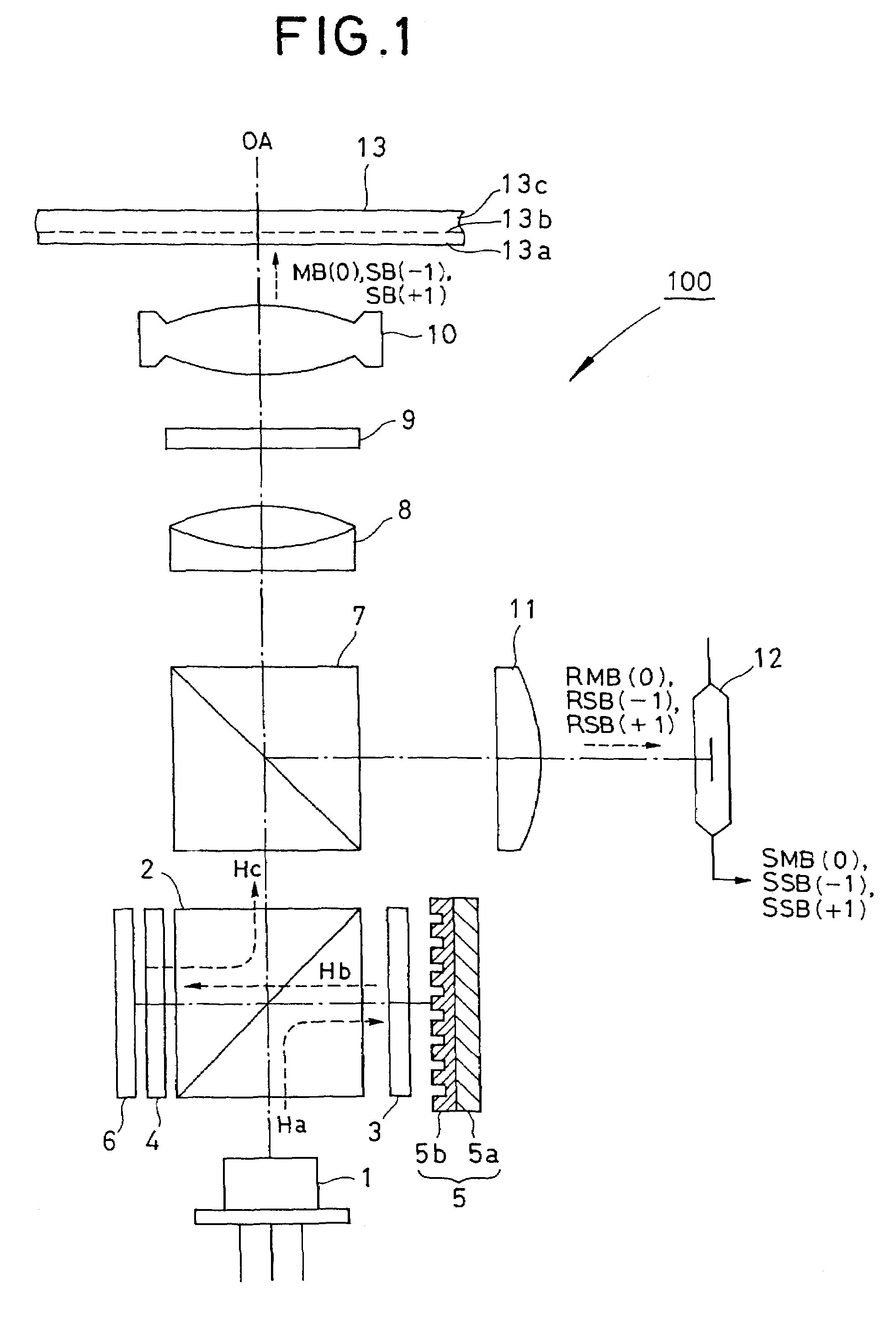
[0048]FIG. 1 is a constructional view showing a construction of a pickup apparatus, FIG. 2 are views showing a structure of a variable optical element, FIG. 3 are views showing a production method of a variable optical element, FIG. 4 is a view for explaining operation of a variable optical element and a pickup apparatus, FIG. 5 is a block diagram showing a construction of an information recording / reproducing apparatus, and FIG. 6 is a block diagram showing a structure of a crosstalk canceller circuit provided in an information recording / reproducing apparatus.

[0049]In FIG. 1, the pickup apparatus 100 comprises: a light source 1 which emits a laser beam Ha, a first beam splitter 2, quarter wavelength plates 3 and 4 which are positioned so that each of them...


PUM

PropertyMeasurementUnit
thicknessaaaaaaaaaa
pitch distanceaaaaaaaaaa
widthaaaaaaaaaa

Abstract

An information recording / reproducing apparatus of the invention is equipped with an objective lens, a light source and a variable optical element having a grating which demonstrates a piezo-electric effect by means of an electric field. The light source emits and irradiates a laser beam onto the grating to generate a 0th order diffraction beam and + / − 1st order diffraction beams in accordance with first order diffraction efficiency, and the objective lens converges the 0th diffraction beam and + / − 1st order diffraction beams which are irradiated onto an information recording medium for the purpose of information recording or information reproducing. By controlling an electric field applied to the grating, the first order diffraction efficiency of the grating is adjusted, whereby light beams are generated which have power levels appropriate for various kinds of information recording media.

Description

[0001]This application is a divisional patent application under 37 C.F.R. § 1.53(b), of prior application Ser. No. 09 / 739,646 filed on Dec. 20, 2000 now U.S. Pat. No. 6,628,599.BACKGROUND OF THE INVENTION[0002]1. Field of the Invention[0003]The present invention relates to a variable optical element that is capable of, for example, altering optical characteristics such as diffraction efficiency, a pickup apparatus that comprises the variable optical element, and an information recording and reproducing apparatus that comprises the pickup apparatus to carry out the recording of information to and reproduction from information recording media.[0004]2. Description of the Related Art[0005]In recent years, information recording media having recordable properties other than information recording media having reproduction-only properties and of a phase-change type have received attention as high-density and large-capacity information recording media. Among the phase-change type information...

Claims


Application Information

Patent Timeline
Patent Type & Authority Patents(United States)
IPC IPC(8): G02F1/00G02B26/00G02B5/18G11B7/135
CPCG11B7/1353G02B5/1828
Inventor MAEDA, TAKANORIOTA, HIROYUKI
Owner PIONEER CORP
Learn More