Eureka AIR delivers breakthrough ideas for toughest innovation challenges, trusted by R&D personnel around the world.

Buffy coat tube and float system and method

a float and tube technology, applied in the field of density-based fluid separation, can solve the problems of catching the constituents of the buffy coat in the analysis area, and achieve the effect of reducing the tolerance precision between the float and the tube, enhancing the buffy coat separation, and reducing the necessary cost of the components

Active Publication Date: 2006-07-11
BATTELLE MEMORIAL INST
View PDF61 Cites 76 Cited by
  • Summary
  • Abstract
  • Description
  • Claims
  • Application Information

AI Technical Summary

Benefits of technology

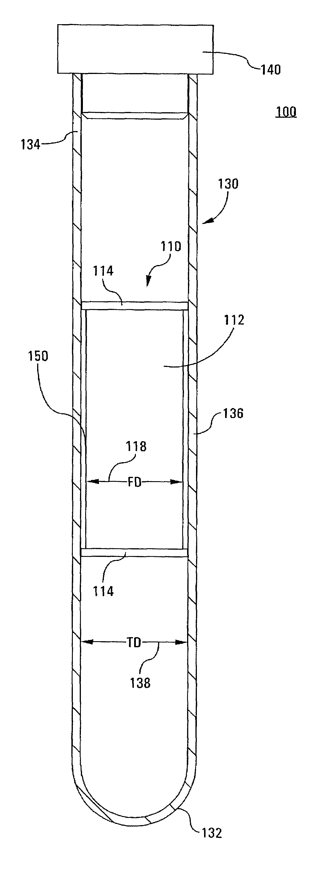
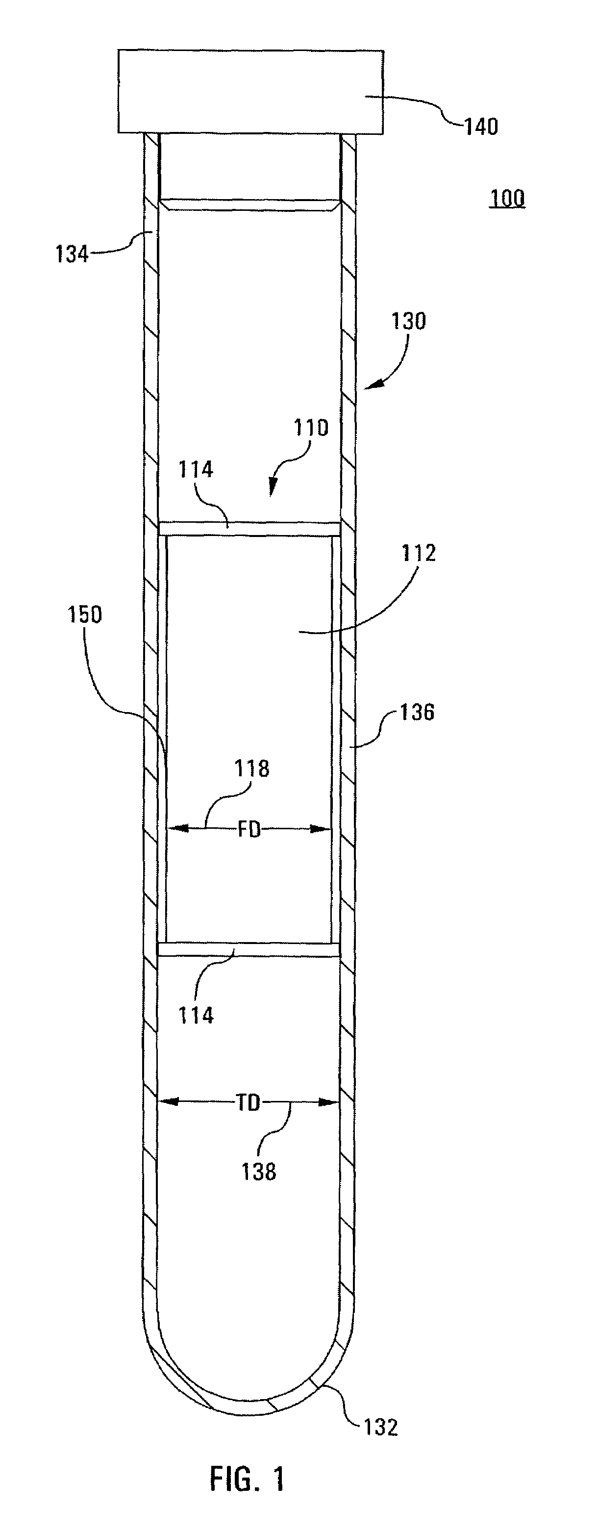
[0017]One advantage of the present invention is found in a blood separating apparatus that can separate the entire buffy coat of a relatively large blood sample from the rest of the blood volume.
[0018]Another advantage of the invention resides in the fact that the buffy coat layers can be made available for visualization or imaging in one simple operation, i.e., the application of pressure and / or centrifugation.
[0019]Still another advantage of the invention resides in enhanced buffy coat separation, retention, and, if desired, removal from the sample tube for further processing.
[0020]Yet another advantage of the invention is found in that the tolerance precision between the float and tube is decreased over that necessary for the prior art QBC-type systems, thus reducing the necessary cost of the components.
[0021]Still another advantage is found in that the tube can be supported for improved imaging of the sample, and a more repeatable depth for imaging may be provided.
[0022]Still further advantages of the present invention reside in its relatively simple construction, ease of manufacture, and low cost.

Problems solved by technology

As a result, the buffy coat constituents are trapped in the analysis areas for review, measurement and / or detection by conventional methods.

Method used


Image

  • Buffy coat tube and float system and method
  • Buffy coat tube and float system and method
  • Buffy coat tube and float system and method

Examples


embodiment 910

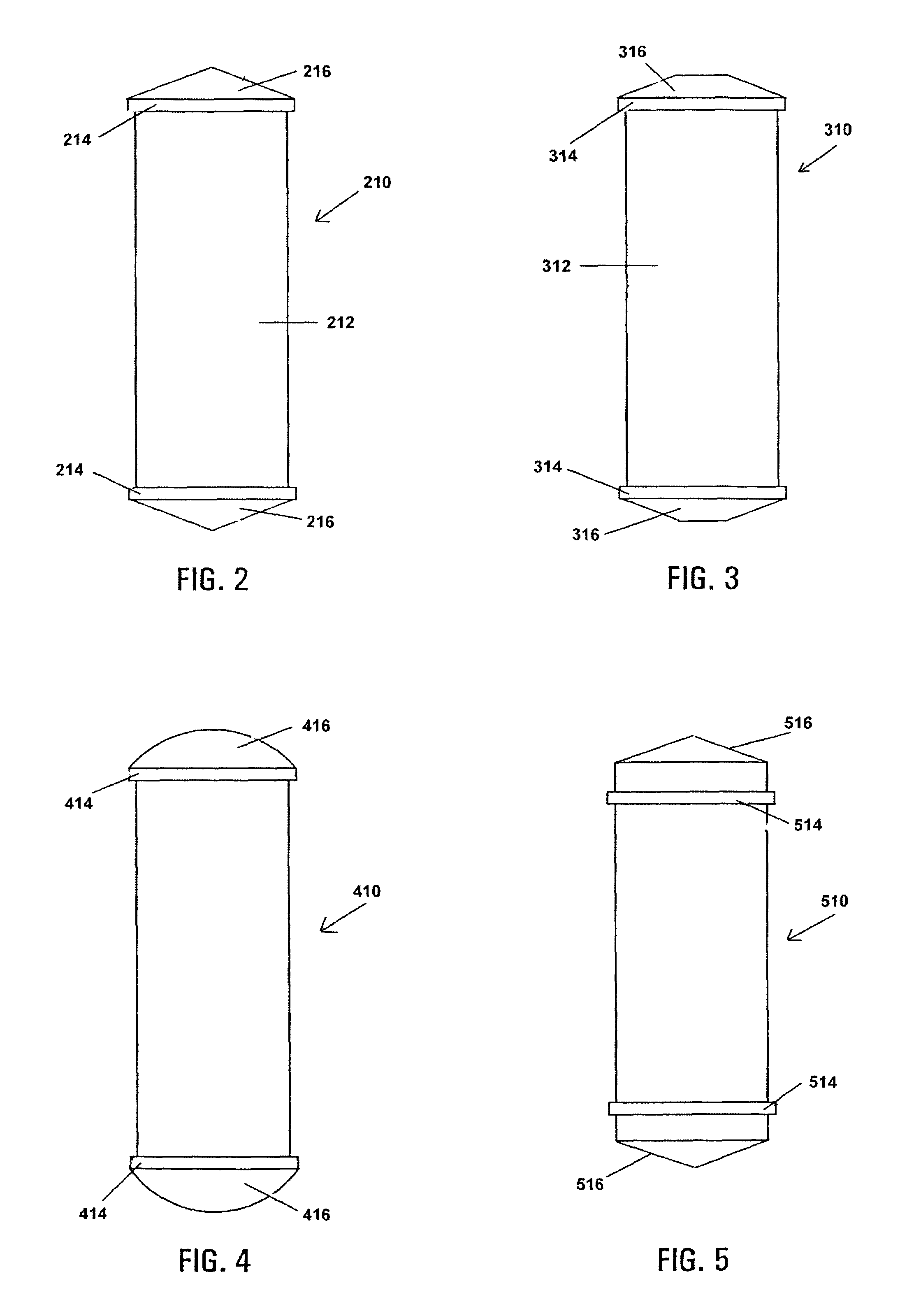
[0080]FIG. 9 illustrates a further float embodiment 910, wherein a helical support member or ridge 920 is provided. That is, instead of discrete annular bands, multiple turns of the helical ridge 920 provides a series of spaced apart ridges on the main body portion 912, which defines a corresponding helical channel 950. The helical ridge 920 is illustrated as continuous, however, the helical band may instead be segmented or broken into two or more segments, e.g., to provide path for fluid flow between adjacent turns of the helical buffy coat retention channel 950. Optional sealing ridges 914 appear at each axial end of the float 910.

[0081]FIGS. 10 and 11 illustrate further ribbed and helical float embodiments 1010 and 1110, respectively. In FIG. 10, annular support ribs 1020, on a main body portion 1012, are tapered in the radial dimension. In FIG. 11, a tapered helical support 1120 appears, formed on a main body portion 1112. The floats 1010 and 1110 are otherwise as described abov...

embodiment 1610

[0084]FIG. 16 illustrates a further splined float embodiment 1610 similar to the float 1410 as shown and described above by way of reference to FIGS. 14 and 15, but wherein optional end sealing ridges are not provided.

[0085]FIGS. 17 and 18 are elevational views of alternative splined floats 1710 and 1810, respectively, and are similar to the respective embodiments shown and described above by way of reference to respective FIGS. 14 and 16, but wherein the axial splines 1724 and 1824, respectively, protruding from respective main body portions 1712 and 1812 are more sparsely radially spaced. The float 1710 includes optional end sealing ridges 1714; such do not appear on the float 1810 of FIG. 18. As above, the respective surfaces 1713 and 1813 may be flat or curved.

[0086]Referring now to FIG. 19, there is shown a perspective view of a splined separator float 1910 in accordance with a further embodiment of the invention. Multiple axially oriented splines 1924 are spaced radially about...


PUM

PropertyMeasurementUnit
volumeaaaaaaaaaa
specific gravityaaaaaaaaaa
densityaaaaaaaaaa

Abstract

A tube and float system for use in separation and axial expansion of the buffy coat is provided. The system includes a transparent, or semi-transparent, flexible sample tube and a rigid separator float having a specific gravity intermediate that of red blood cells and plasma. The sample tube has an elongated sidewall having a first cross-sectional inner diameter. The float consists of a main body portion and one or more support members protruding from the main body portion to engage and support the sidewall of the sample tube. The main body portion and the support members of the float have a cross-sectional diameter less than that of the first cross-sectional inner diameter of the tube when the sample tube is expanded, such as by centrifugation. The main body portion of the float together with an axially aligned portion of the sidewall define an annular volume therebetween. The support members protruding from the main body portion of the float traverse said annular volume to produce one or more analysis areas. During centrifugation, the centrifugal force enlarges the diameter of the tube to permit density-based axial movement of the float in the tube. Thereafter, the centrifugal force is reduced to cause the tube sidewall to return to its first diameter, thereby capturing the float and trapping the buffy coat constituents in the analysis area. The buffy coat constituents can then be evaluated or measured.

Description

FIELD OF THE INVENTION[0001]The present invention relates generally to density-based fluid separation and, in particular, to an improved sample tube and float design for the separation and axial expansion of constituent fluid components layered by centrifugation, and a method employing the same. The present invention finds particular application in blood separation and axial expansion of the buffy coat layers, and will be described with particular reference thereto. However, it will be recognized that the present invention is also amenable to other like applications.BACKGROUND OF THE INVENTION[0002]Quantitative Buffy Coat (QBC) analysis is routinely performed in clinical laboratories for the evaluation of whole blood. The buffy coat is a series of thin, light-colored layers of white cells that form between the layer of red cells and the plasma when unclotted blood is centrifuged or allowed to stand.[0003]QBC analysis techniques generally employ centrifugation of small capillary tube...

Claims


Application Information

Patent Timeline
Patent Type & Authority Patents(United States)
IPC IPC(8): G01N33/96B01L3/00B01L3/14G01N33/49
CPCB01L3/50215B01L3/505Y10S436/81G01N33/49Y10S435/81B01L2400/0409
Inventor HAUBERT, THOMASWARDLAW, STEPHEN C.
Owner BATTELLE MEMORIAL INST
Why Eureka
Eureka Blog
Learn More