Eureka AIR delivers breakthrough ideas for toughest innovation challenges, trusted by R&D personnel around the world.

Separating device for the bodywork of a vehicle

a bodywork and vehicle technology, applied in the direction of roofs, transportation items, tank vehicles, etc., can solve the problems of increasing the stiffness of the bodywork, not optimizing the arrangement in respect and not always expedient, so as to reduce the weight of the component, the bodywork stiffness is higher, and the effect of reducing the weigh

Inactive Publication Date: 2006-07-11
DAIMLER AG
View PDF10 Cites 6 Cited by
  • Summary
  • Abstract
  • Description
  • Claims
  • Application Information

AI Technical Summary

Benefits of technology

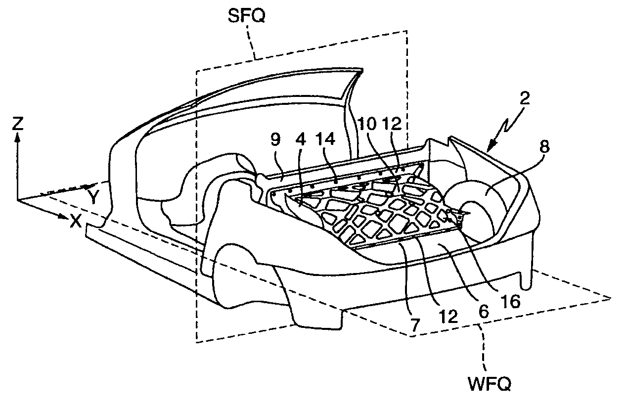
[0008]A novel separating arrangement according to the invention is fitted releasably in the front part of a rear compartment of a motor vehicle. It serves inter alia to partition off a fuel tank compartment from the rear compartment. The separating arrangement is positioned in such a manner that it is curved in relation to a vertical transverse plane of the vehicle (SFQ) and a horizontal transverse plane of the vehicle (WFQ). The separating arrangement is preferably curved concavely in relation to these planes but, given an appropriate distribution of space between the fuel tank compartment and rear compartment, a convex curvature may also be expedient. The curvature increases the bodywork stiffness in comparison with the prior art.
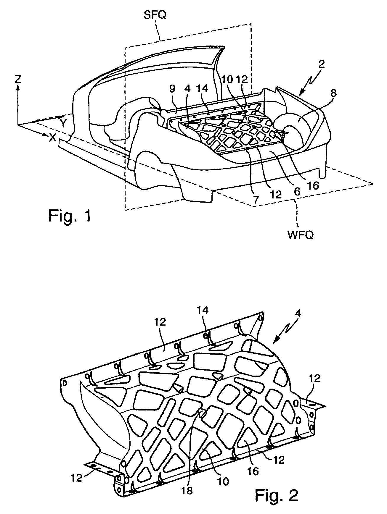
[0009]A further novel feature is that the separating arrangement has increased material thickness along the calculated force flow lines. Accordingly, material may be saved outside the force flow lines, this leading to a reduction in weight while simultaneously increasing the stiffness. The force flow lines are calculated for the corresponding bodywork with reference to standard loading situations (e.g. torsion and bending of the bodywork) with the aid of the finite element method. According to the invention, the force flow line profile is applied to the separating arrangement.
[0010]In a further advantageous refinement, the separating arrangement has, at its edges, fastening surfaces which are formed approximately parallel to the vertical or horizontal transverse planes of the vehicle. This results in a greater compensation of tolerance in two directions in space during the assembly of the body shell.
[0012]The separating arrangement is preferably fastened directly to the vehicle bodywork by screwing. Additional elements, such as angled components and rails, may be omitted. The number of screws is reduced. This measure contributes to the reduction in weight.
[0014]The abovementioned casting processes make it possible to fashion the separating arrangement according to the invention from light metals and, in particular, to vary the wall thicknesses in accordance with the invention. This results in a lower component weight and in a higher bodywork stiffness. Suitable casting metals are aluminum alloy and magnesium alloy and what is referred to as AZ91.

Problems solved by technology

However, the increase in the bodywork stiffness is often associated with an increase in the vehicle weight, since a number of measures are frequently associated with additional or stronger bodywork components.
However, the arrangement is not optimized in respect of a reduction in weight.
Sandcasting processes or gravity chill casting are possible, but are not always expedient because of cost.
However, this requires an additional working step and possibly an additional punching tool.

Method used


Image

  • Separating device for the bodywork of a vehicle
  • Separating device for the bodywork of a vehicle

Examples


Embodiment Construction

[0021]The detail illustrated in FIG. 1 of the self-supporting bodywork 2 comprises a rear compartment 6 which is separated from a fuel tank compartment (not illustrated specifically) by means of a separating arrangement 4. The separating arrangement 4 extends from a base 7 of the rear compartment 6 as far as a crossmember 9 and between two wheel houses 8, of which only the right-hand one can be seen in the perspective illustration. The separating arrangement 4 has a curvature in relation to a horizontal transverse plane of the vehicle WFQ and a vertical transverse plane of the vehicle SFQ.

[0022]A detailed illustration of the separating arrangement 4 is provided by FIG. 2. The curvature of the separating plane is designed concavely in relation to the WFQ and the SFQ, this bringing about an enlargement of the fuel tank compartment. The separating arrangement 4 has reinforcing struts 10 which correspond to the force flow directions, which are dependent on the type of vehicle.

[0023]The ...


PUM


Abstract

A separating arrangement for the self-supporting bodywork of a motor vehicle has a partition which is arranged at the front end of a rear compartment, extends in the transverse direction of the vehicle and over part of its height between rear wheel houses of the motor vehicle and is fastened to boundary walls of the rear compartment. The separating arrangement is designed as a supporting device which strengthens the bodywork against distortion. The separating arrangement is curved in relation to a vertical transverse plane of the vehicle and a horizontal transverse plane of the vehicle, and the separating arrangement has reinforcing struts in the form of greater material thickness along force flow lines.

Description

BACKGROUND AND SUMMARY OF THE INVENTION[0001]This invention relates to a separating arrangement.[0002]The “bodywork stiffness” is increasingly regarded as one of the most important criteria for modern motor vehicles. It makes a decisive contribution to safety, high-quality appearance and comfort. However, the increase in the bodywork stiffness is often associated with an increase in the vehicle weight, since a number of measures are frequently associated with additional or stronger bodywork components.[0003]German document DE 198 43 025 C1 describes the possibility of increasing the bodywork stiffness while reducing the mass using a component used as standard, a dividing wall of the fuel tank. The dividing wall is of flat configuration and is virtually parallel to a vertical transverse plane of the vehicle. Angled elements and rails, with which the separating arrangement is fastened releasably to the bodywork, are in turn fastened to the dividing wall. In addition, the separating ar...

Claims


Application Information

Patent Timeline
Patent Type & Authority Patents(United States)
IPC IPC(8): B62D25/08B62D25/00
CPCB62D25/087
Inventor ERNEY, THOMASSEITZ, DANIELASEEFRIED, JOHANN
Owner DAIMLER AG
Why Eureka
Eureka Blog
Learn More