
Mass spectrometer

a mass spectrometer and mass filter technology, applied in mass spectrometers, isotope separation, particle separator tubes, etc., can solve the problems of loss, poor duty cycle, and other parent ions are effectively attenuated by the mass filter,

Active Publication Date: 2006-07-04
MICROMASS UK LTD
View PDF46 Cites 54 Cited by
  • Summary
  • Abstract
  • Description
  • Claims
  • Application Information

AI Technical Summary

Benefits of technology

[0011]The preferred ion trap when incorporated into a mass spectrometer enables a high duty cycle to be obtained for both MS and MS / MS modes of operation.

Problems solved by technology

A problem with known tandem mass spectrometers is that the duty cycle can be relatively poor in applications where there is a need to identify or quantify many different components from a sample.
The poor duty cycle is due to the fact that whilst parent ions having a desired mass to charge ratio are transmitted through the mass filter all other parent ions are effectively attenuated by the mass filter and are lost.

Method used


Image

  • Mass spectrometer
  • Mass spectrometer
  • Mass spectrometer

Examples


Embodiment Construction

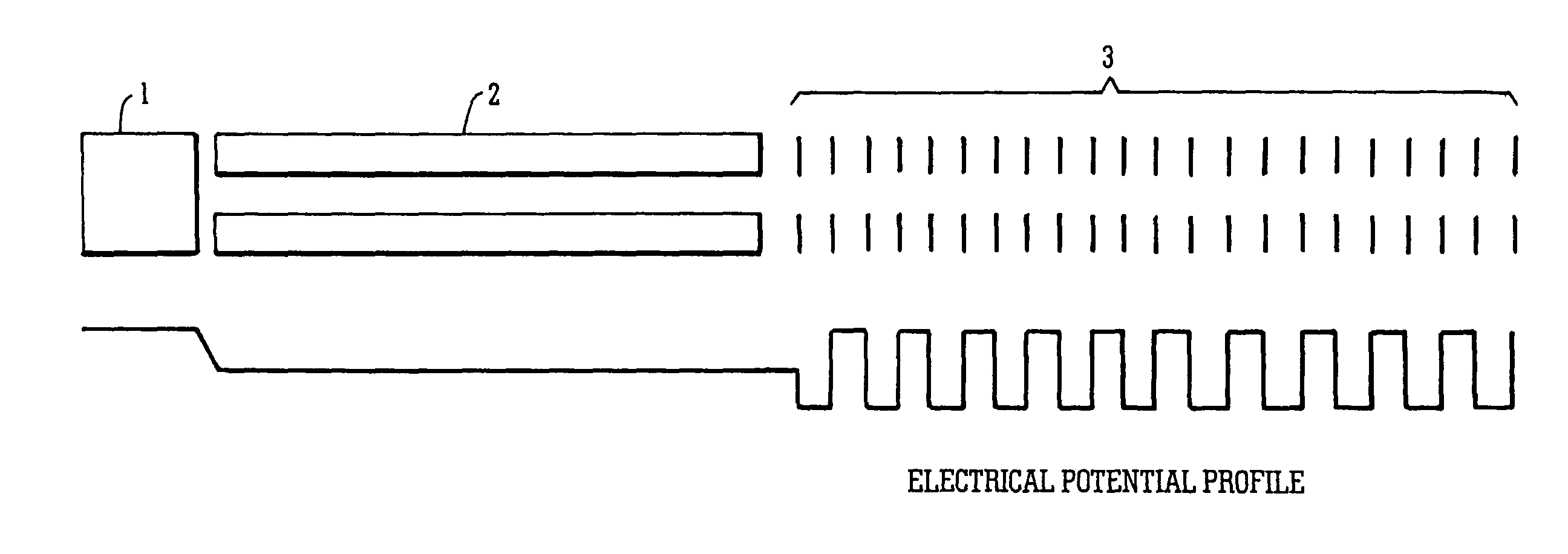
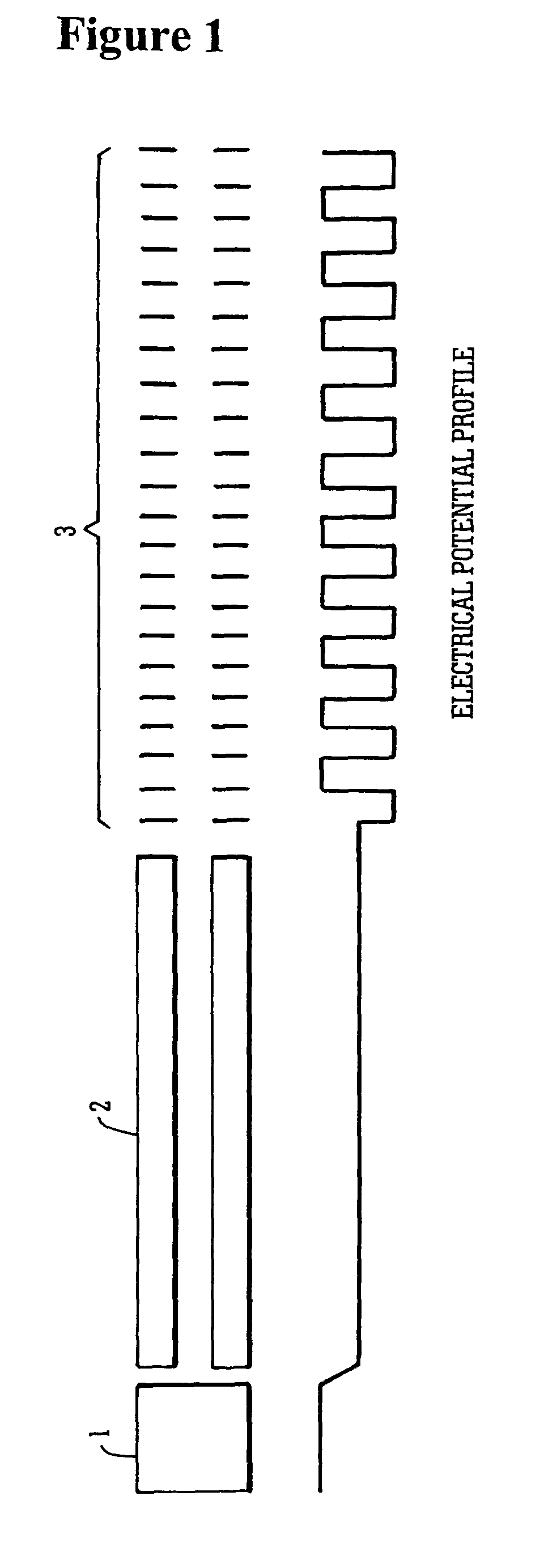
[0104]A preferred embodiment will now be described with reference to FIG. 1. Ions may be released from e.g. a pulsed ion source 1 such as a laser ablation or a Matrix Assisted Laser Desorption / Ionisation (MALDI) ion source 1. Alternatively, a pulse of ions may be released from an ion trap (not shown). The pulse of ions is then preferably accelerated through a constant potential difference so that the ions gain a constant energy. The ions are then preferably transmitted to a field free region 2 which is preferably maintained at a relatively low pressure (e.g. −4 mbar). Ions having different mass to charge ratios will travel through the field free region 2 at different velocities and the ions will therefore become temporally dispersed according to their mass to charge ratios.

[0105]The ions upon reaching the end of the field free region 2 are then arranged to exit the field free region 2 and enter an AC or RF ion guide / ion trap 3 operated according to the preferred embodiment. Ions hav...


PUM


Abstract

A mass spectrometer is disclosed comprising an ion trap wherein ions which have been temporally separated according to their mass to charge ratio or ion mobility enter the ion trap. Once at least some of the ions have entered the ion trap, a plurality of ion trapping regions are created along the length of the ion trap in order to fractionate the ions. Alternatively, the ions may be received within one or more axial trapping regions which are translated along the ion trap with a velocity which is progressively reduced to zero.

Description

CROSS-REFERENCE TO RELATED APPLICATIONS[0001]This application claims the benefit of the filing of U.S. Provisional Patent Application Ser. No. 60 / 427,559 filed Nov. 20, 2002.BACKGROUND OF THE INVENTION[0002]1. Field of the Invention[0003]The present invention relates to a mass spectrometer and a method of mass spectrometry.[0004]2. Discussion of the Prior Art[0005]A common form of tandem mass spectrometry (MS / MS) involves transmitting ions emitted from an ion source through a mass filter arranged upstream of a gas collision cell. The mass filter is set so that only ions having a specific mass to charge ratio are onwardly transmitted to the gas collision cell. Ions having other mass to charge ratios are attenuated by the mass filter. Ions transmitted by the mass filter then enter the gas collision cell and are induced to fragment. Fragment ions formed within the gas collision cell exit the gas collision cell and are then mass analysed by, for example, an orthogonal acceleration Time ...

Claims


Application Information

Patent Timeline
IPC IPC(8): H01J49/40H01J49/00H01J49/42
CPCH01J49/4225
Inventor BATEMAN, ROBERT HAROLDGILES, KEVINHOYES, JOHN BRIANPRINGLE, STEVEBROWN, JEFF
Owner MICROMASS UK LTD
Learn More