Eureka AIR delivers breakthrough ideas for toughest innovation challenges, trusted by R&D personnel around the world.

Image processing device and image processing method for correction of image distortion

a technology of image processing and image distortion, which is applied in the field of image processing devices and image processing methods, can solve the problems of image distortion, image quality degradation, and difficulty in distinguishing the edge of the original from the pattern of the desk, and achieves the effect of rapid and correct finding of image distortion

Inactive Publication Date: 2006-06-20
MINOLTA CO LTD
View PDF15 Cites 77 Cited by
  • Summary
  • Abstract
  • Description
  • Claims
  • Application Information

AI Technical Summary

Benefits of technology

[0024]The present invention is made to solve the above-described problems and one object of the present invention is to provide an image processing device and an image processing method allowing rapid and correct finding of a distortion of an image obtained by an image pick-up of an original by a digital camera or the like.
[0025]Another object of the present invention is to provide an image processing device allowing a correction of an image distorted due to an effect of a swing even when an object does not include a rectangular area or the entire object is not included in the image.
[0026]Still another object of the present invention is to provide an image processing device allowing a rapid and correct correction of an image distorted due to an effect of a swing.

Problems solved by technology

Now, when an image of an original representing information such as characters and photographs is to be picked up by a digital camera, for example, the picked-up image becomes distorted due to a swing of a lens of the digital camera.
When an area extracted through the area determination processing includes a part which should be included in a different area, an optimal image processing or compression processing cannot be performed, resulting in the degradation of image quality, compression ratio and so on.
Even if the edge of the original is included in the obtained image, when the image of the original is picked up together with the image of a desk, for example, on which the original resides, the pattern on the desk may be shown in the background and makes it difficult to distinguish the edge of the original from the pattern of the desk.
However, depending on the zoom magnification and the position of pick-up, the entire object may not be included in the picked-up image.
Specifically, when the image of the original is picked up by a digital camera, if the zoom magnification is high or the distance between the digital camera and the original is short, it is impossible to place the original as a whole into the scope of the camera allowing the pick up.
Therefore, when the object is not entirely included in the image, an appropriate correction cannot be performed according to U.S. Pat. No. 5,528,194.
Additionally, though in the technique described in Japanese Patent Laying-Open 10-200836, the reference pattern is projected onto the screen, it is not easy to measure the distortion of the reference pattern projected on the original.
This is because that the condition of image pick-up is different from time to time and the image pick-up is not always performed under the sufficient light and that it is difficult to distinguish a design pattern on the original from the reference pattern as the design pattern is shown on the original in various forms such as characters, photograph, and so on.

Method used


Image

  • Image processing device and image processing method for correction of image distortion
  • Image processing device and image processing method for correction of image distortion
  • Image processing device and image processing method for correction of image distortion

Examples


first embodiment

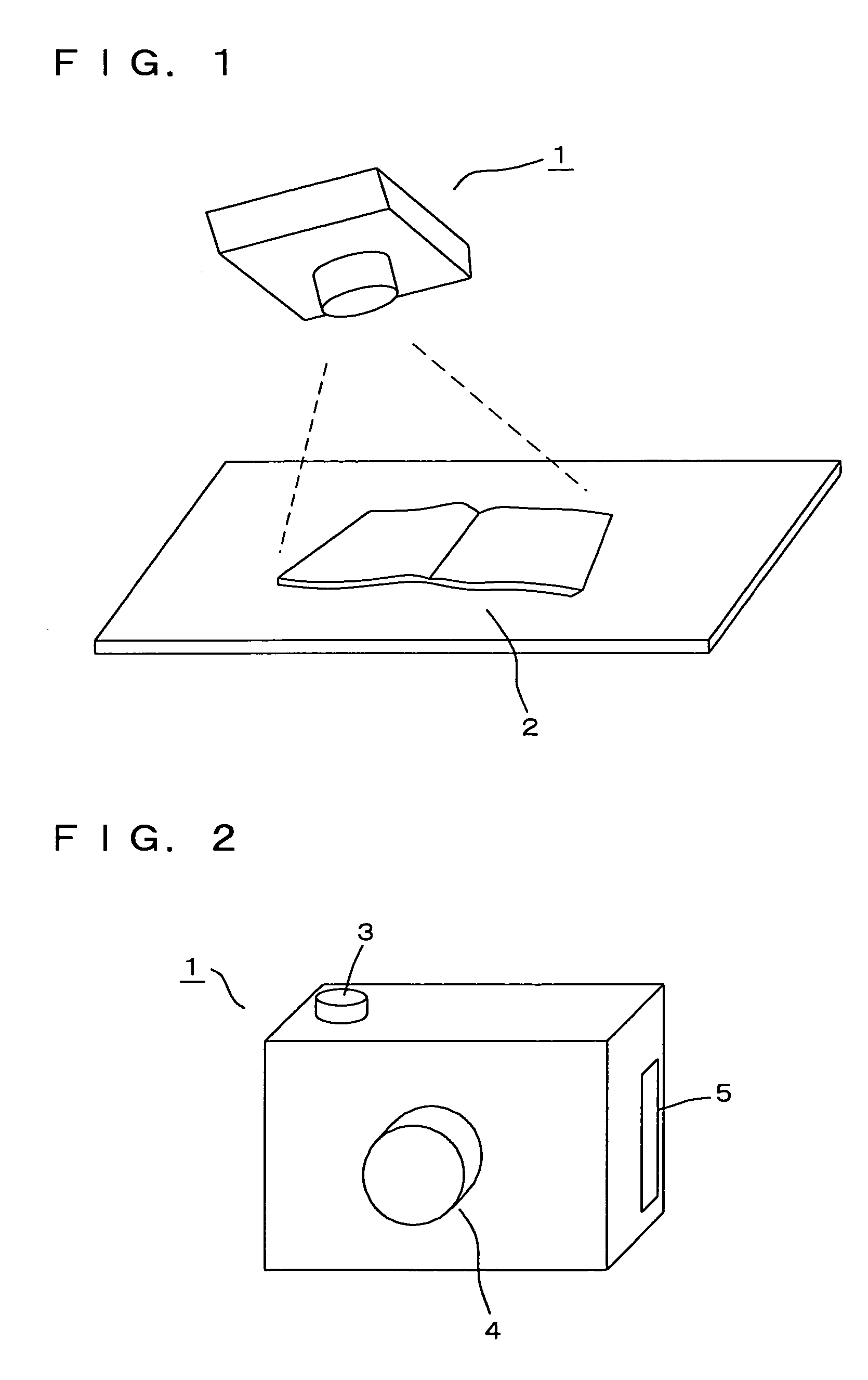
[0084]With reference to FIG. 1, in the first embodiment, relative misalignment of a digital camera 1 and an original 2 is detected from an image obtained from image pick-up of original 2 by digital camera 1.

[0085]FIG. 2 is a perspective view of a digital camera 1 from a side of a lens. With reference to FIG. 2, digital camera 1 includes a pick-up button 3, a pick-up lens portion 4 and a card insertion inlet 5.

[0086]The result of image pick-up by digital camera 1 is stored as electronic data in a hard disc card (not shown) inside digital camera 1. Here, the hard disc card is a recording medium of image data and hard disc cards compliant with PCMCIA (Personal Computer Memory Card Interface Association) standard, for example, can be employed as such. Alternatively, a memory card can be employed. As a recording medium, mini discs (MDs) can be used as well. Alternatively, digital camera 1 can be directly connected to a printer or the like via an SCSI (Small Computer System Interface) cab...

second embodiment

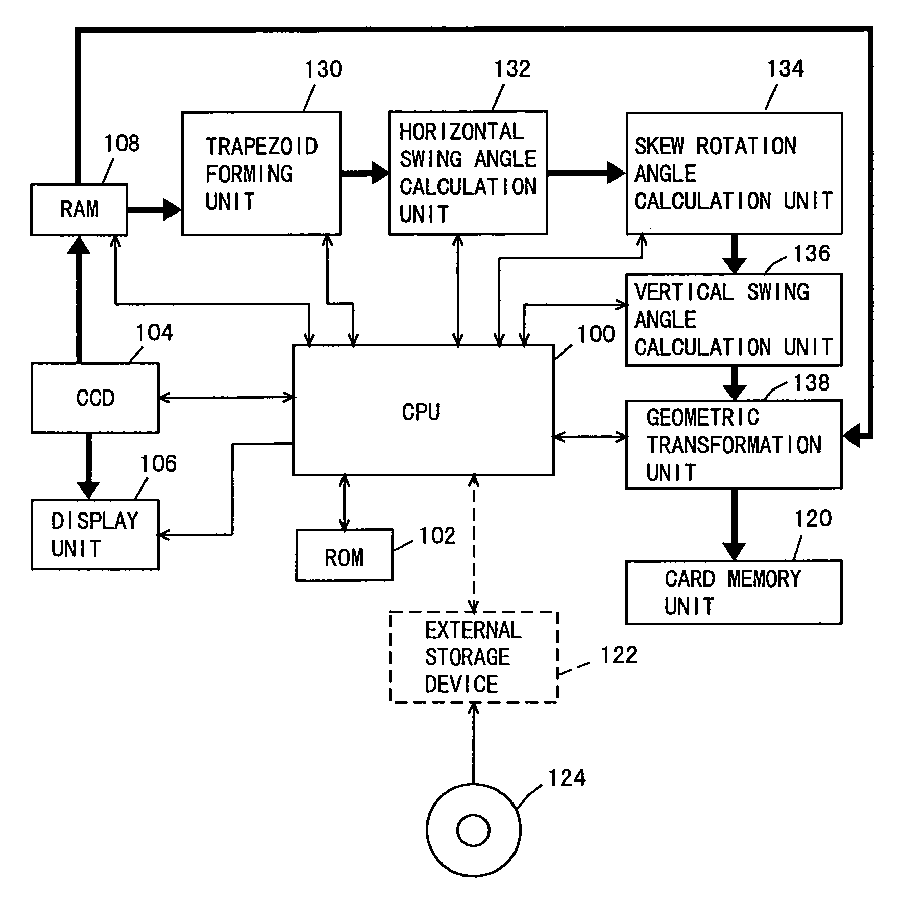
[0129]Next, a digital camera with an image processing device according to the second embodiment will be described. FIG. 12 is a block diagram showing a circuit structure of digital camera 1 according to the second embodiment. With reference to FIG. 12, digital camera 1 includes CPU 100 performing an overall control of digital camera 1, CCD 104 performing an image pick-up, display unit 106 displaying a content of the image pick-up, RAM 108 temporarily storing the image from CCD 104, a trapezoid forming unit 130 forming a trapezoid based on the picked-up image, a horizontal swing angle calculation unit 132 finding a swing angle in a horizontal direction based on the formed trapezoid, a skew rotation angle calculation unit 134 finding a skew rotation angle in a direction of rotation based on the found trapezoid, a vertical swing angle calculation unit 136 finding a swing angle in a vertical direction based on the found trapezoid, a geometric transformation unit 138 performing a geometr...


PUM


Abstract

For finding an inclination of an image rapidly and correctly, an image processing device includes a CCD picking up an image, an edge detection unit detecting an edge of an image relating to the picked-up image, a rotation unit rotating the detected edge in an image plane, an operation unit deriving a characteristic amount of rotated edge and an inclination detection unit detecting an inclination of the picked-up image based on the derived characteristic amount.

Description

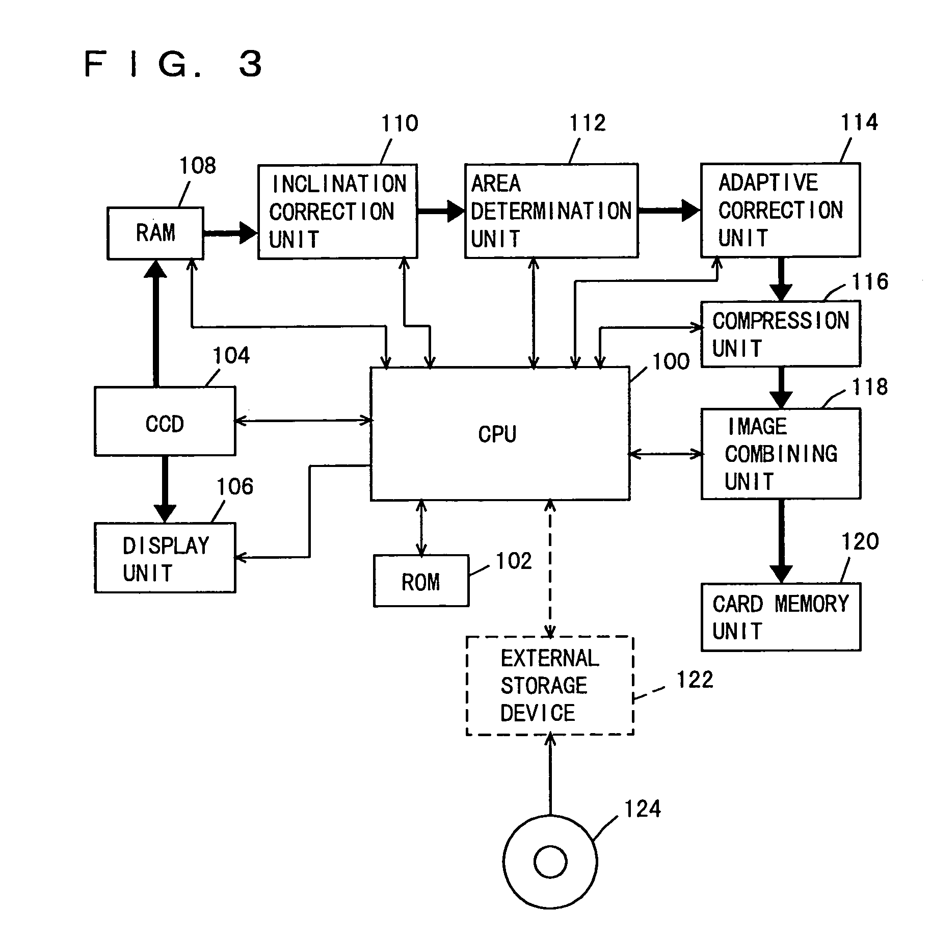
[0001]This application is based on applications Nos. 11-078214 and 11-185967 filed in Japan, the contents of which are hereby incorporated by reference.BACKGROUND OF THE INVENTION[0002]1. Field of the Invention[0003]The present invention relates to image processing devices and image processing methods. More particularly, the present invention relates to image processing devices and image processing methods allowing correction of image distortion produced by relative misalignment of an original and a camera at the time of image pick-up.[0004]2. Description of the Related Art[0005]Recently, digital cameras have become quite popular. The digital cameras enable the image pick-up and storage in the form of digital data of originals on which photographs or characters are printed. In digital cameras, usually the picked-up images are first subjected to an image processing for removal of noise from the image and then to a compression processing for reducing the data amount. A different image...

Claims


Application Information

Patent Timeline
Patent Type & Authority Patents(United States)
IPC IPC(8): G06K9/36G06K9/32G06T3/00G06T5/00H04N1/387H04N5/262
CPCG06K9/3283H04N5/2628H04N1/387G06T5/006G06V30/1478G06T5/80
Inventor HORIE, DAISAKU
Owner MINOLTA CO LTD
Why Eureka
Eureka Blog
Learn More