
Measurement arrangement for X-ray fluoresence analysis

a fluorescence analysis and measurement arrangement technology, applied in the field of using x-ray fluorescence analysis, can solve the problems of clumsy overall appearance of the apparatus, constant need for flushing, and inability to flush the required purity of the gas, etc., and achieve the effect of small size and convenient servi

Inactive Publication Date: 2006-06-20
OXFORD INSTR IND ANALYSIS OY +1
View PDF15 Cites 27 Cited by
  • Summary
  • Abstract
  • Description
  • Claims
  • Application Information

AI Technical Summary

Benefits of technology

[0011]It is an objective of the present invention to provide a measurement arrangement for X-ray fluorescence analysis that does not need flushing with any externally provided gas. Another objective of the invention is to provide a measurement arrangement for the X-ray fluorescence analysis of liquid samples where unintentional changes in measurement geometry can be prevented. A yet other objective of the invention is to provide a measurement apparatus for X-ray fluorescence analysis, which apparatus is small-sized and compact and easily serviceable.
[0017]According to a second aspect of the invention certain structural and operational parameters of the measurement arrangement are selected in a way that optimises portability and easy handling. For example, it appears to be advantageous to select the excitation radiation among the so-called L-lines of an X-ray tube with an anode made of silver, rhodium or molybdenium. The X-ray tube may be of the end window or the side window type. Beryllium of appropriately selected thickness is a preferred choice for various windows in the structure, but can in many cases be replaced with polyimide or polycarbonate. It is also advantageous to use a collimator between the X-ray tube and the sample, and to match the material of the collimator with the anode material of the X-ray tube so that possible fluorescent radiation produced in the collimator material will add the overall intensity of available excitation radiation.

Problems solved by technology

The 3 keV line of argon causes little interference with these measurements, but the absorption of the fluorescent radiation in air becomes a problem—hence the need for gas flushing.
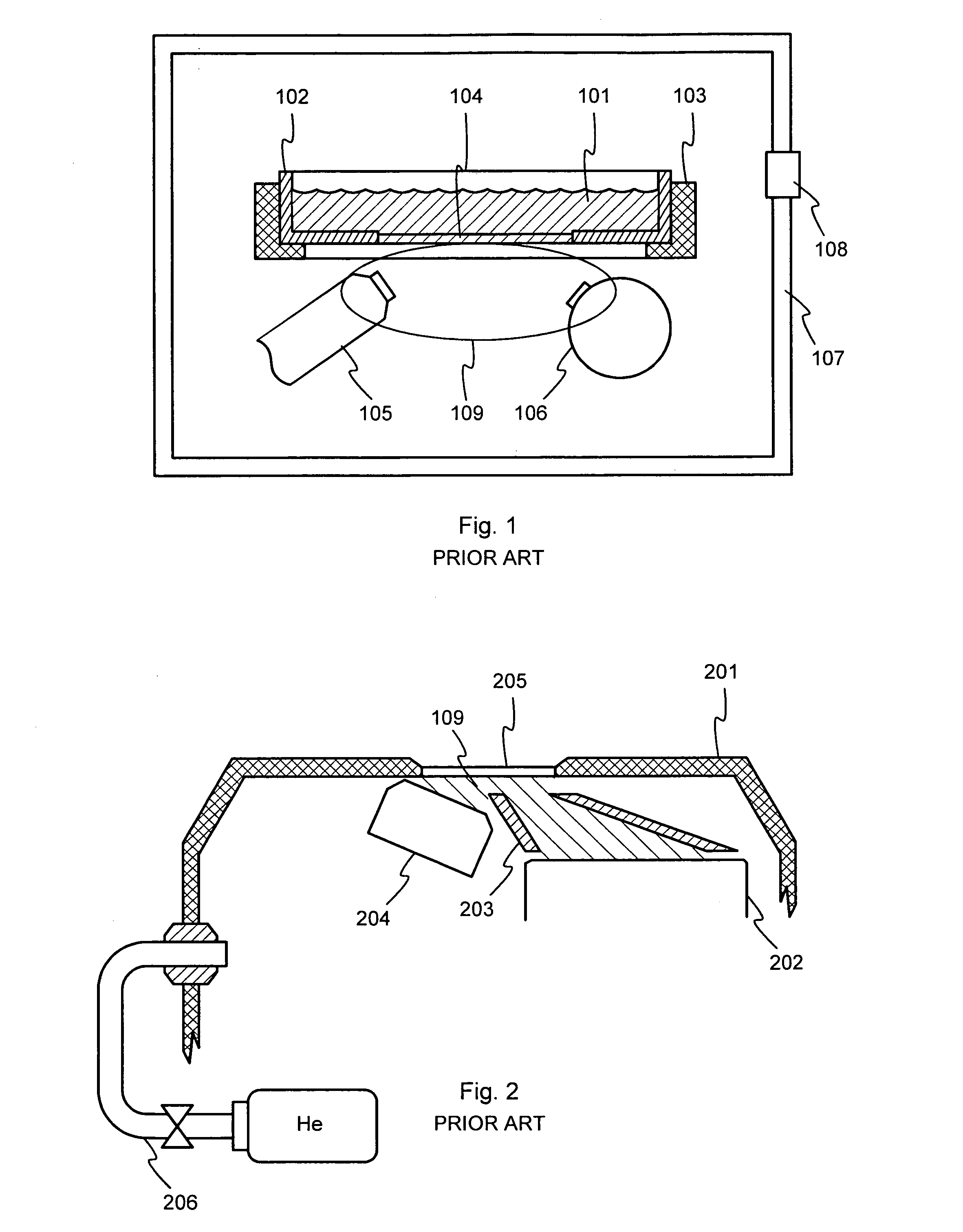
The constant need for flushing is a problem, because flushing gases of the required purity are not cheap, because the required settling time before the actual measurement can begin is relatively long and because the gas containers and tubing tend to make the overall appearance of the apparatus somewhat clumsy.
However, concerning the application shown in FIG. 1, liquid hydrocarbons are highly volatile even at normal atmospheric pressure, and exposing them to a vacuum would cause the whole sample to evaporate very quickly.
Eliminating an empty space between the X-ray source, the window and the detector altogether has not been regarded as a feasible solution either.
Direct propagation of X-rays from the X-ray source to the detector must not be possible.
Yet another known drawback of the prior art arrangement is the possible change in measurement geometry, caused by creeping deformation of the window.
This is a problem especially in the case of FIG. 1.
Being made of a polymer, typically polypropylene, and being constantly exposed to hydrocarbon solvents, the window material is prone to stretching.
Even if a careful selection of materials could prevent any damage caused by chemical incompatibility, it is possible that a person conducting the measurement uses a too heavy sample or leaves the sample in the cup for an extensively long time, in which case the sheer mechanical load can cause a permanent deformation of the window 104.

Method used


Image

  • Measurement arrangement for X-ray fluoresence analysis
  • Measurement arrangement for X-ray fluoresence analysis
  • Measurement arrangement for X-ray fluoresence analysis

Examples


Embodiment Construction

[0030]The exemplary embodiments of the invention presented in this patent application are not to be interpreted to pose limitations to the applicability of the appended claims. The verb “to comprise” is used in this patent application as an open limitation that does not exclude the existence of also unrecited features. The features recited in depending claims are mutually freely combinable unless otherwise explicitly stated.

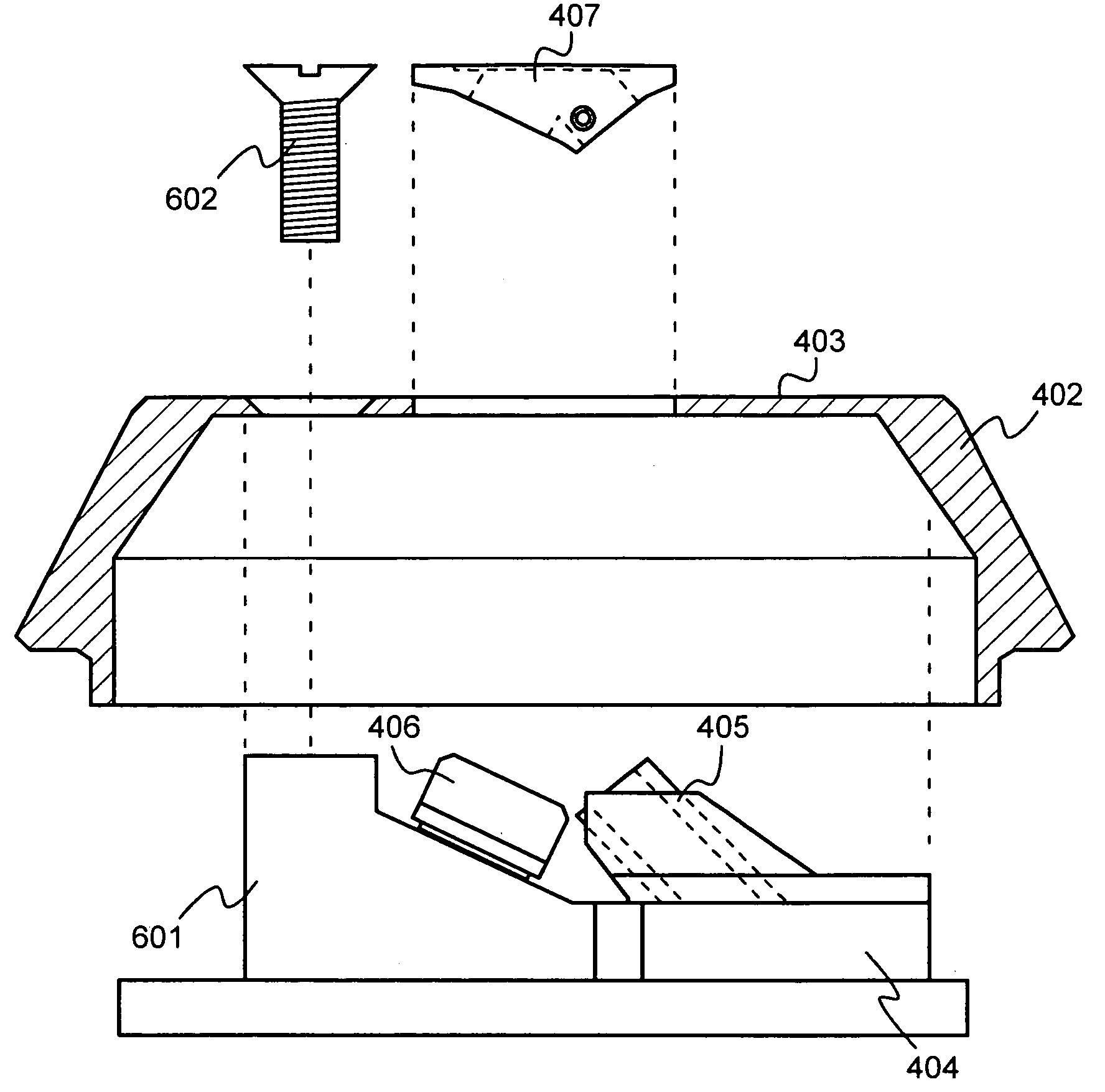
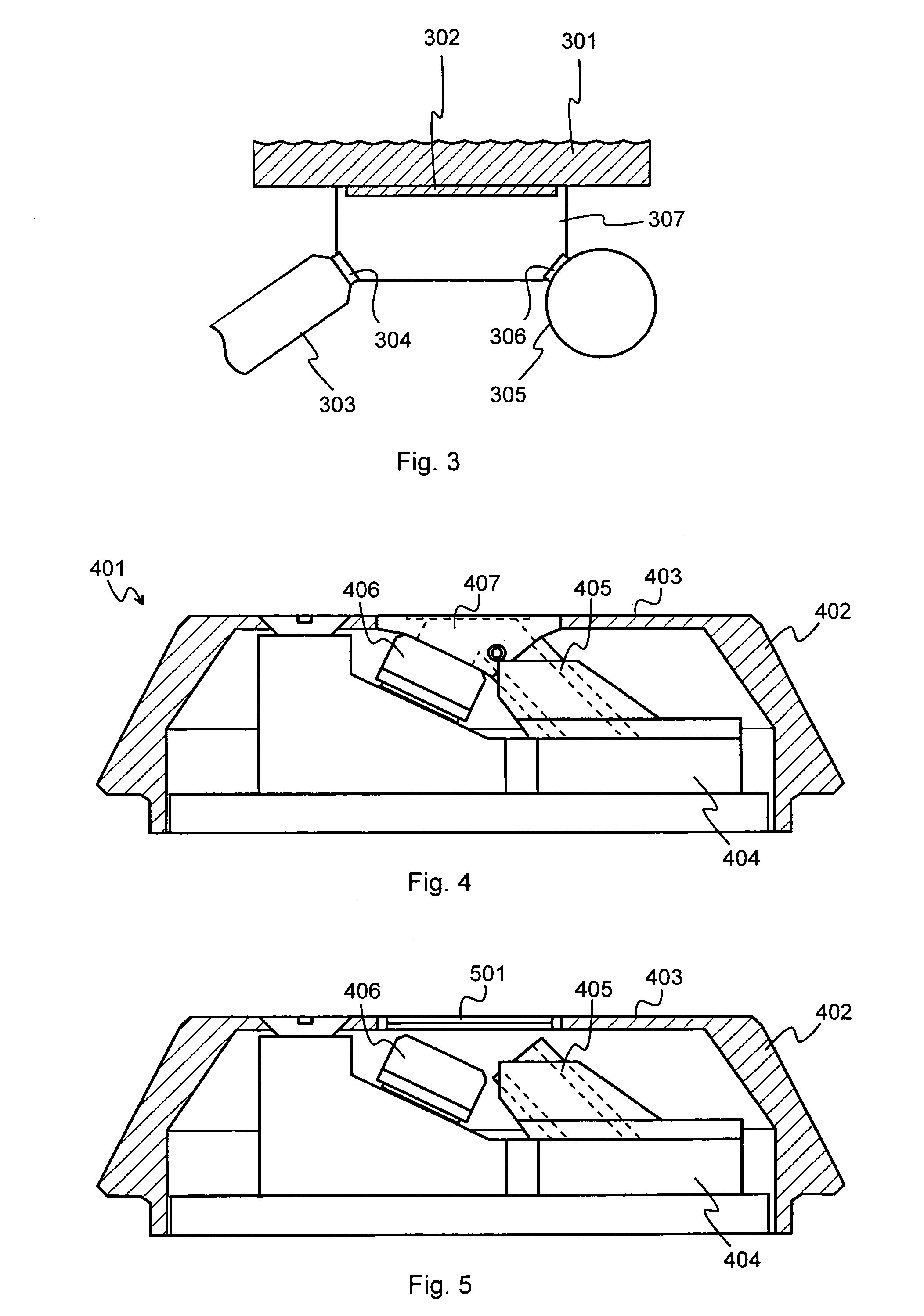
[0031]FIG. 3 illustrates schematically the principle of using a separate gas enclosure according to an embodiment of the invention. For the purpose of performing an X-ray fluorescence analysis, there is a sample 301 of a liquid substance that is to be analysed. A window 302 made of a material substantially transparent to X-rays offers an air-free interface to the sample. For the purpose of unambiguity, the window 302 is here designated as the sample window. The interface being air-free means that considering the spatial region where X-ray illumination and fluores...


PUM

PropertyMeasurementUnit
thicknessaaaaaaaaaa
thicknessaaaaaaaaaa
thicknessaaaaaaaaaa

Abstract

A portable measurement apparatus is presented for inducing and measuring fluorescent X-ray radiation. It comprises an X-ray source (303, 902, 1005, 1105) adapted to controllably irradiate a sample (301, 803) with X-rays, and a detector (305, 406, 1006, 1106) adapted to detect fluorescent radiation emitted by said sample (301, 803). The X-ray source (303, 902, 1005, 1105) is an X-ray tube, an anode of which comprises at least one of silver, rhodium and molybdenium. Consequently said X-ray tube is adapted to controllably emit L-line radiation of at least one of silver, rhodium and molybdenium.

Description

TECHNICAL FIELD[0001]The invention concerns generally the technology of using X-ray fluorescence analysis for analysing the contents of samples. Especially the invention concerns the problem of how should the measurement apparatus be constructed so that the detection of very small impurity concentrations with even relatively soft X-rays would be possible.BACKGROUND OF THE INVENTION[0002]X-ray fluorescence analysis is a common and widely used tool in analysing the contents of certain elements and / or compounds in given samples. As a first example we will consider the task of analysing the sulphur content of liquid hydrocarbons, such as petrol (gasoline), diesel oil and other liquid fuels. Environmental considerations have promoted the enactment of relatively tight limits for allowable sulphur content in liquid fuels. A measurement arrangement should be able to reliably measure concentrations in the order of only few ppm (parts per million).[0003]FIG. 1 illustrates schematically a prio...

Claims


Application Information

Patent Timeline
Patent Type & Authority Patents(United States)
IPC IPC(8): G01N23/223
CPCG01N23/223G01N2223/076
Inventor SIPILA, HEIKKI JOHANNESKAIJANSAARI, RIITTA
Owner OXFORD INSTR IND ANALYSIS OY
Learn More