
Method and apparatus of M/r imaging with coil calibration data acquisition

Inactive Publication Date: 2006-06-20
GENERAL ELECTRIC CO
View PDF7 Cites 41 Cited by
  • Summary
  • Abstract
  • Description
  • Claims
  • Application Information

AI Technical Summary

Benefits of technology

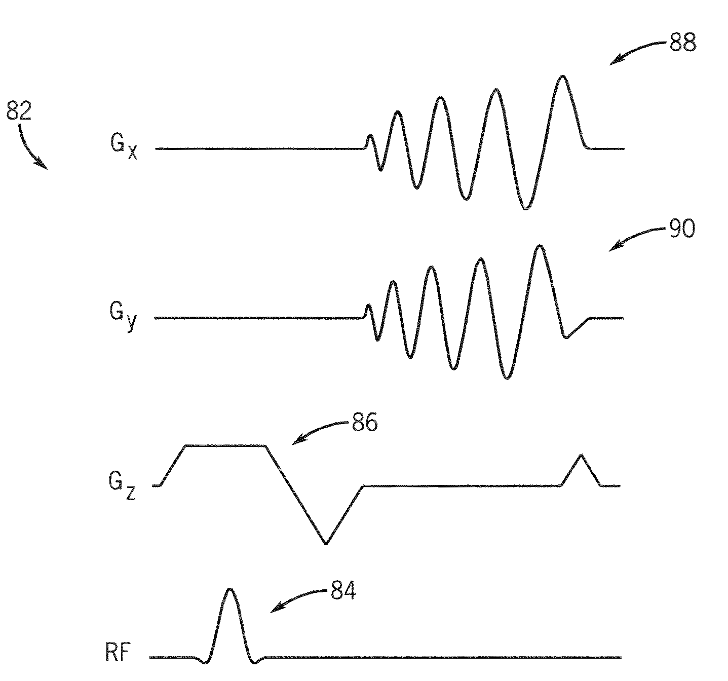
[0011]The present invention provides a system and method of MR imaging that overcomes the aforementioned drawbacks. The imaging technique of the present invention acquires a reduced set of MR data that is appended to or interleaved with MR data acquired from an MR imaging scan to measure or otherwise determine coil sensitivity to an imaging volume. With the present invention, a navigated calibration data acquisition short in duration is carried out immediately prior to a parallel imaging scan, such as SENSE or SMASH. The navigated data acquisition is carried out immediately before the imaging data acquisition so that the probability of subject motion is reduced. Additionally, the parameters of the navigated calibration scan as well as the scan volume can be set to solely depend upon the receive coils thereby providing higher calibration signal and full FOV coverage. Additionally, the scan time is reduced when compared to the scan times typically associated with self-calibration techniques. Moreover, operator involvement is significantly reduced for the calibration data acquisition thereby increasing convenience, usability, and throughput while eliminating the likelihood of operator error in the scan volume prescription. In addition, the present invention can acquire coil sensitivity data using the same plane orientation as the imaging data acquisition scan. The present invention is also applicable with a number of types of imaging sequences including, but not limited to FSE, FGRE, EPI, and spiral imaging.
[0013]In accordance with another aspect of the present invention, an MRI apparatus includes a plurality of gradient coils positioned about a bore of a magnet to impress a polarizing magnetic field. An RF transceiver system and an RF switch are controlled by a pulse module to transmit and receive RF signals to and from an RF assembly to acquire MR images. The MRI apparatus further includes a computer programmed to apply a navigated calibration pulse sequence between applications of an imaging pulse sequence to acquire calibration data indicative of B1 field strength across an FOV. The computer is further programmed to apply a parallel imaging sequence to acquire MR data for image reconstruction. The computer is also programmed to reconstruct an image of a subject from MR data acquired from an array of surface coils and use the acquired calibration data to reduce aliasing in the image.
[0014]According to another aspect of the present invention, the invention is embodied in a computer program stored on a computer readable storage medium and having instructions which, when executed by a computer, cause the computer to define an FOV. The computer is also caused to play out a calibration sequence to acquire low resolution MR data from the FOV indicative of field strength sensitivities in an array of surface coils. The computer is also caused to apply an imaging sequence after application of the calibration sequence to acquire imaging data from the FOV with the array of surface coils. The set of instructions then causes the computer to reduce artifacts in the imaging data caused by the field strength sensitivities.

Problems solved by technology

Expeditiously executing an MR scan not only increases patient throughput but also reduces the likelihood of motion-induced artifacts in the reconstructed images.
The external calibration method, while reasonably effective, does have drawbacks.
For instance, the external calibration method can give rise to artifacts in the reconstructed image if the subject moves between application of the calibration scan and the imaging data acquisition (SENSE or SMASH scan).
This can be particularly problematic for axial planes with breathholding if the breathhold size between the two scans is different.
That is, scanning a calibration volume that is smaller than the imaging data volume, or mis-centering the calibration volume, will result in slices that cannot be unwrapped or have poor alias unwrapping.
Further, if multiple scan stations are used for parallel imaging at each station, the calibration volume must be prescribed for each station thereby further increasing the burden imposed on the operator when prescribing the calibration scan volume and location.
Similar to the external calibration method, however, the self or auto-calibration technique also has several drawbacks.
That is, aliasing in the calibration data results in incomplete unwrapping of aliasing in the SENSE or SMASH acquired data.
Moreover, since SENSE or SMASH-prescribed scans deliberately provide very low signal from static tissue, for instance, vascular imaging with paramagnetic contrast agents such as gadolinium, the resulting calibration will, therefore, also have very low signal which may negatively affect the accuracy of the acquired sensitivity data.

Method used


Image

  • Method and apparatus of M/r imaging with coil calibration data acquisition
  • Method and apparatus of M/r imaging with coil calibration data acquisition
  • Method and apparatus of M/r imaging with coil calibration data acquisition

Examples


Embodiment Construction

[0022]A system is shown to acquire MR data consistent with the principles of parallel imaging. In this regard, the imaging system includes, as will be described in greater detail below, a phased-array coil arrangement to acquire MR data from an FOV. As described above, parallel imaging is a data acquisition technique that is often used for those applications where it is desired to expedite the acquisition of MR data from a subject. Further, the present invention will be described with respect to a spiral sampling of k-space. One skilled in the art will appreciate that the present invention is equivalently applicable with other types of fast acquisitions such as FSE, FGRE, EPI, and the like.

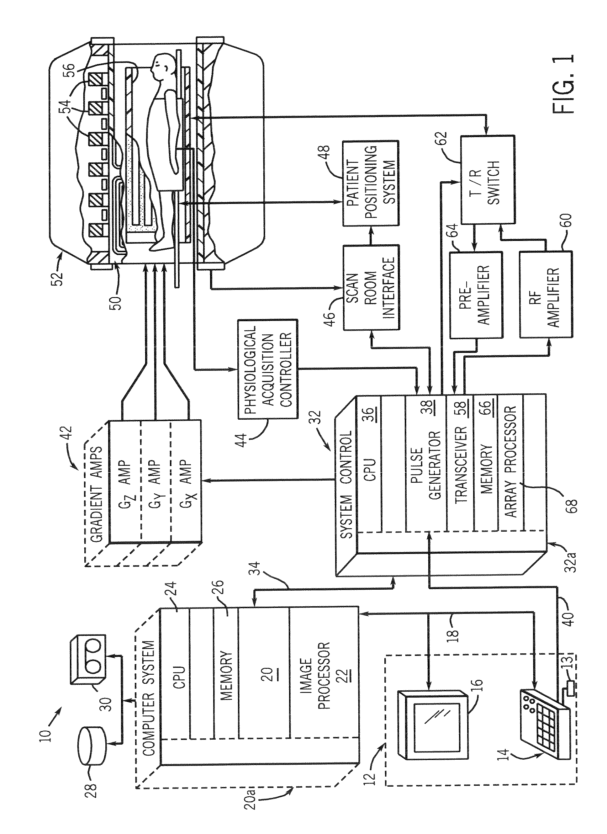
[0023]Referring now to FIG. 1, the major components of a preferred magnetic resonance imaging (MRI) system 10 incorporating the present invention are shown. The operation of the system is controlled from an operator console 12 which includes a keyboard or other input device 13, a control panel 14,...


PUM


Abstract

A system and method for MR imaging with coil sensitivity or calibration data acquisition for reducing wrapping or aliasing artifacts is disclosed. Low resolution MR data representative of coil sensitivity of a coil arrangement within an FOV is acquired prior to application of an imaging data acquisition scan and is used to reduce wrapping or aliasing artifacts in a reconstructed image.

Description

BACKGROUND OF INVENTION[0001]The present invention relates generally to fast MR imaging and, more particularly, to MR imaging with the acquisition of coil sensitivity calibration data.[0002]When a substance such as human tissue is subjected to a uniform magnetic field (polarizing field B0), the individual magnetic moments of the spins in the tissue attempt to align with this polarizing field, but precess about it in random order at their characteristic Larmor frequency. If the substance, or tissue, is subjected to a magnetic field (excitation field B1) which is in the x-y plane and which is near the Larmor frequency, the net aligned moment, or “longitudinal magnetization”, MZ may be rotated, or “tipped”, into the x-y plane to produce a net transverse magnetic moment Mt. A signal is emitted by the excited spins after the excitation signal B1 is terminated and this signal may be received and processed to form an image.[0003]When utilizing these signals to produce images, magnetic fiel...

Claims


Application Information

Patent Timeline
IPC IPC(8): G01V3/00
CPCG01R33/5611
Inventor KING, KEVIN F.ANGELOS, ELISABETHPOLZIN, JASON A.
Owner GENERAL ELECTRIC CO
Learn More