
High purity sputter targets with target end-of-life indication and method of manufacture

a sputter target and end-of-life technology, applied in the field of cathodic sputtering methods and equipment, can solve the problems of severe damage to the sputtering chamber, affecting the quality of sputtering, and uneven erosion of the surface of the targ

Inactive Publication Date: 2006-06-20
TOSOH SMD
View PDF12 Cites 26 Cited by
  • Summary
  • Abstract
  • Description
  • Claims
  • Application Information

AI Technical Summary

Benefits of technology

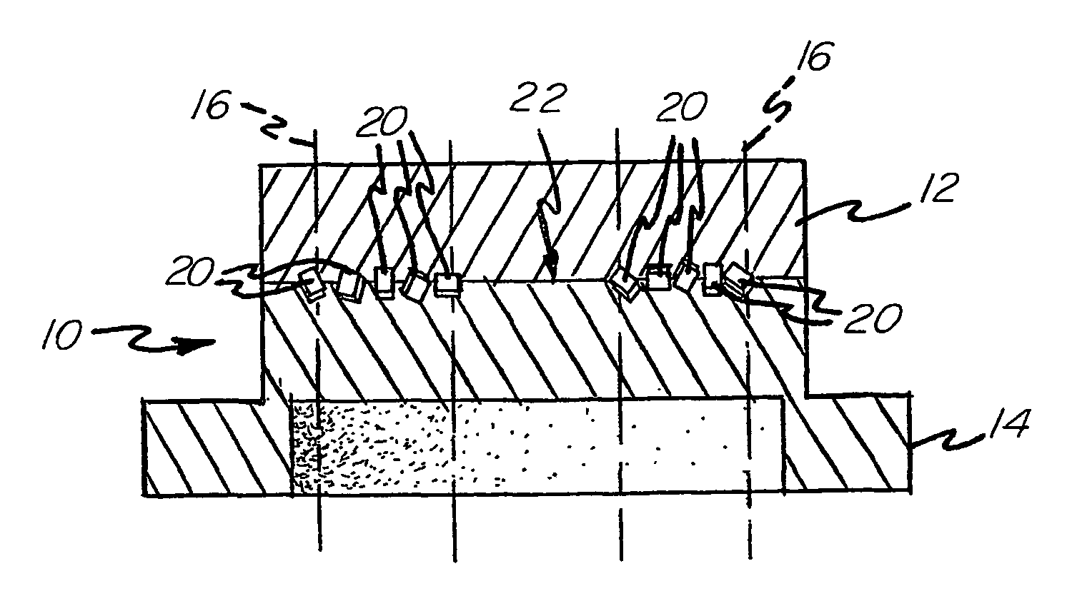
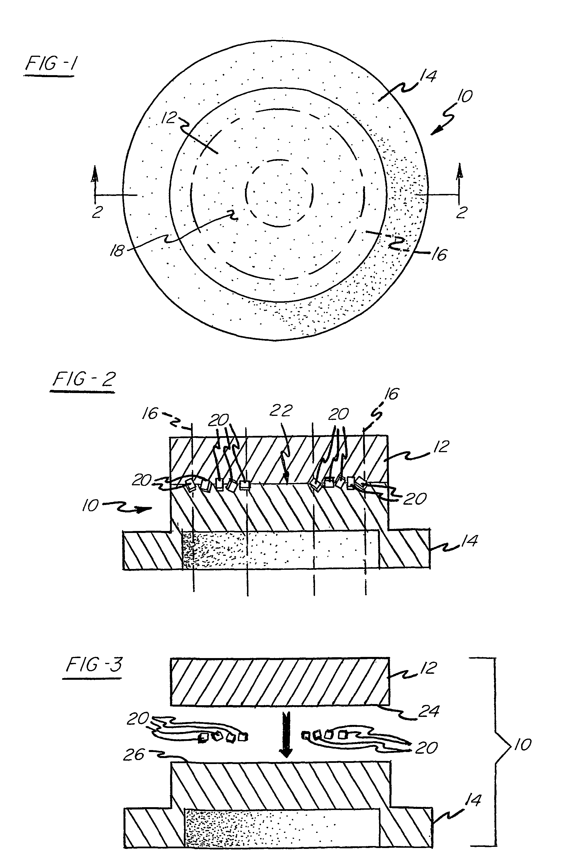
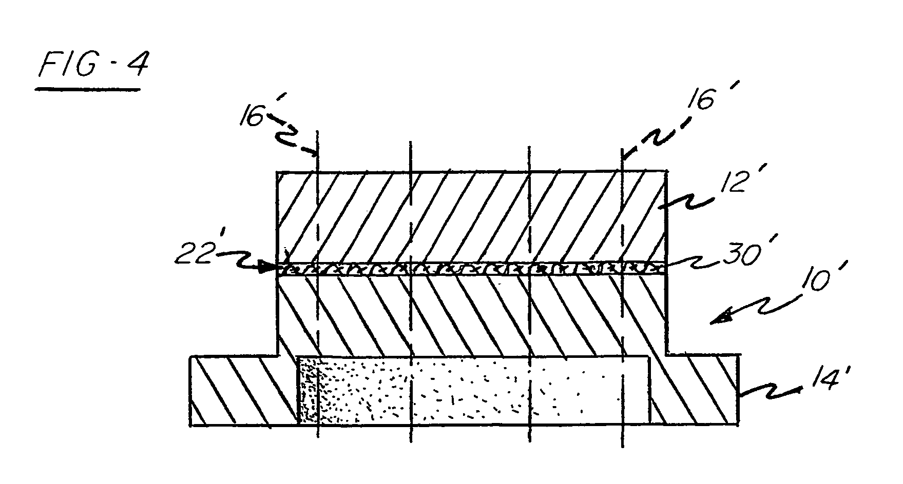
[0012]These needs and others are addressed by a preferred sputter target assembly comprising a target, a backing plate bonded to the target along an interface and dielectric particles located proximate to that interface. A preferred method for manufacturing the sputter target assembly comprises the steps of providing the target and the backing plate; distributing the dielectric particles between mating surfaces of the target and the backing plate, most preferably along a sputtering track on one of the mating surfaces; and bonding the target to the backing plate along the mating surfaces. Exemplary target materials for use in the method include high purity metals such as aluminum, co

Problems solved by technology

Generally, this erosion is not uniform across the surface of the target.
The burn-through of the interface will be referred to hereinafter as a “target end-of-life condition.” Continued sputtering after the target end-of-life condition is reached leads to the possibility of contamination of the substrate due to sputtering of the backing plate material or, when no backing plate is present, to the possibility of rupture and severe damage to the sputtering chamber due to re-pressurization of the chamber or leakage of heat exchange fluid.
On the other hand, it is undesirable to continue use of a target after a target end-of-life condition is reached.
Although it is known to monitor target life by maintaining a count of the number of sputtering cycles in which a particular target has been used, it is possible for the counter to be reset or for the user to be overly aggressive in target consumption.
Each of these techniques has the drawback that the detection of a target end-of-life condition is dependent on the diligence of the operator throughout the sputtering process.
The use of a backing plate material visually distinguishable from the target material has the additional drawback that visually distinguishable materials also likely will have different electrical and thermal properties, thereby increasing the impedance as well as the risk of differential expansion between the two materials.
When a target end-of-life condition occurs, these pockets of pressurized gas are ruptured, thereby increasing the pressure within the sputtering chamber.
One drawback to this technique is the difficulty of forming such pockets of pressurized gas during the fabrication of the sputter target assembly.
Another drawback is that the thermal conductivity of the pressure gas will likely be less than that of the surrounding target and backing plate materials, thereby risking thermal damage to the sputter target assembly.
In the past, the occurrence of such arcs have been considered undesirable, since they tend to cause localized heating of the sputter surface.
This localized heating increases the risk of macroparticle ejection, that is, the ejection of unusually large particles or droplets of sputtering material deleterious to the uniformity of the thin film of sputtering material formed on the substrate.

Method used


Image

  • High purity sputter targets with target end-of-life indication and method of manufacture
  • High purity sputter targets with target end-of-life indication and method of manufacture
  • High purity sputter targets with target end-of-life indication and method of manufacture

Examples


example

[0055]A study was performed on 12.98 inch aluminum alloy targets to evaluate the usefulness of the preferred methods and apparati of the invention in indicating target end-of-life conditions. Eight radial stripes of boron nitride paint were applied on rear surfaces of two of the targets across the main sputter track of each. Eight radial stripes of a ceramic paste containing aluminum oxide were applied on a rear surface of a third target across the main sputter track. In the latter case, the rear surface of the third target was first roughened using a handheld engraver with a sharp carbide tip. A ceramic paste comprising aluminum oxide in a silicone-based liquid sold under the trademark CERAMABOND 552 by Aremco Products, Inc. of Valley Cottage, N.Y. was then painted onto the roughened portions of the rear surface of the third target. The paste was allowed to air dry for 15 minutes and then the target was bonded to a backing plate by vacuum electron beam welding. The two targets pain...


PUM

PropertyMeasurementUnit
Diameteraaaaaaaaaa
Diameteraaaaaaaaaa
Dielectric polarization enthalpyaaaaaaaaaa

Abstract

A preferred sputter target assembly (10, 10′) comprises a target (12, 12′), a backing plate (14, 14′) bonded to the target (12, 12′) along an interface (22, 22′) and dielectric particles (20, 20′) between the target (12, 12′) and the backing plate (14, 14′). A preferred method for manufacturing the sputter target assembly (10, 10′) comprises the steps of providing the target (12, 12′) and the backing plate (14, 14′); distributing the dielectric particles (20, 20′) between mating surfaces (24, 26) of the target (12, 12′) and the backing plate (14, 14′), most preferably along a sputtering track pattern on one of the mating surfaces; and bonding the target (12, 12′) to the backing plate (14, 14′) along the mating surfaces (24, 26). A preferred method for sputtering in accordance with the invention comprises the steps of applying electrical power to the sputter target (50, 160); causing the sputter target assembly (50, 160) to produce an electromagnetic signal (not shown) when a target end-of-life condition exists; and monitoring the sputter target assembly (50, 160) to detect the electromagnetic signal.

Description

CROSS-REFERENCE TO RELATED APPLICATIONS[0001]Priority filing benefit of (1) International PCT application PCT / US01 / 41775 filed Aug. 17, 2001, and published under PCT 21(2) in the English language; (2) U.S. Provisional Application Ser. No. 60 / 226,073 filed Aug. 17, 2000; 60 / 241,060 filed Oct. 17, 2000.FIELD OF THE INVENTION[0002]This invention relates to cathodic sputtering methods and apparatus, and, more specifically, to methods and apparatus relating to sputter target assemblies providing electromagnetic signals representative of target end-of-life conditions.BACKGROUND OF THE INVENTION[0003]Cathodic sputtering is widely used for the deposition of thin layers of material onto substrates. Basically, a sputtering process requires gas ion bombardment of a target formed from a material that is to be deposited as a thin film or layer on a given substrate. During such a process, the target is positioned such that a sputtering surface of the target faces the substrate across a chamber wh...

Claims


Application Information

Patent Timeline
IPC IPC(8): C23C14/34H01J37/34
CPCC23C14/3407C23C14/3414H01J37/3491H01J37/3435H01J37/3482H01J37/3426C23C14/34
Inventor IVANOV, EUGENE Y.SMATHERS, DAVID B.WICKERSHAM, JR., CHARLES E.POOLE, JOHN E.
Owner TOSOH SMD
Learn More