High speed motor coils

a high-speed motor and coil technology, applied in the direction of dynamo-electric machines, synchronous generators, electrical apparatus, etc., can solve the problems of limiting the rotational speed of the flywheel, the difficulty of rotating the flywheel at relatively high speeds, so as to reduce the air gap and the size of the motor, reduce the air gap, and the effect of increasing efficiency

Inactive Publication Date: 2006-06-13
AFS TRINITY POWER CORP
View PDF14 Cites 16 Cited by
  • Summary
  • Abstract
  • Description
  • Claims
  • Application Information

AI Technical Summary

Benefits of technology

[0009]This overlapping coil configuration is beneficial because there are no coils that are disposed in an end to end configuration. Thus, the jogging or change in torque when the rotor passes by an end of a magnet is eliminated. A more even or constant torque is generated by the field windings during the 360-degree rotation of the rotor.
[0010]In another preferred embodiment, each of the coil windings may further have a jogged or bent portion that connects the first part to the second part. The jogged or bent portion permits the windings to be more closely nestled. This reduces the air gap and the size of the motor, which makes the motor more efficient.
[0011]In yet another preferred embodiment, the coils so that the left end of each coil overlaps a portion of the right end of an adjacent coil. This eliminates the between the coils, which further reduces the air gap. This improves efficiency and the smoothness of the torque, which prevents or eliminates cogging.

Problems solved by technology

Rotating flywheels at relatively high speeds presents difficulties.
These difficulties limit the flywheel's rotational speed, and therefore the amount of power that can be stored in the flywheel.
One difficult with rotating a flywheel or any rotor at a relatively high speed with a motor is rippling or a variation in the torque which will cause variations in the speed and cause the rotor or flywheel to vibrate excessively or wobble and become damaged.
One cause of this is the configuration of field windings in motors.
This can cause cogging of the rotor, which is detrimental to the rotor and can result in structural failure.
Another problem with motors is eddy currents.
When rotating fast enough, eddy currents can nullify the driving force or generate sufficient heat so as to cause structural failure.

Method used


Image

  • High speed motor coils
  • High speed motor coils
  • High speed motor coils

Examples


Embodiment Construction

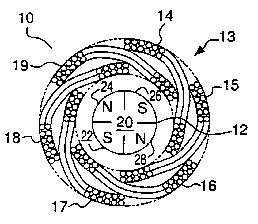
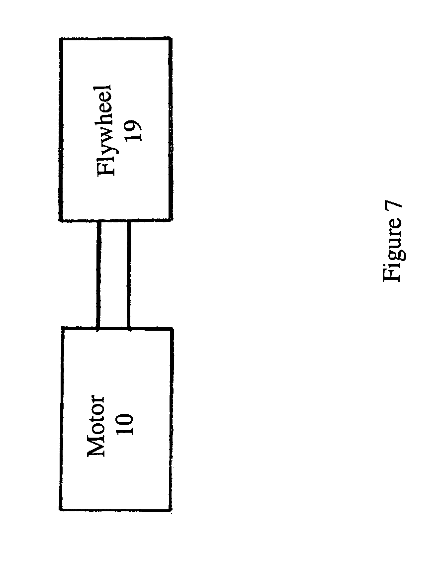
[0020]A schematic cross-section of an embodiment of this invention is set forth in FIG. 1. The motor 10 of this invention preferably includes a rotor 12 and a stator 13 as shown in FIG. 1. FIG. 1 is a cross-sectional schematic depiction of the motor rotor 12 and stator 13. Attached to the rotor 12 may be one or more flywheels 19 (see FIG. 7). The rotor 12 includes permanent magnets. The rotor 12 may have any number of permanent magnets. In the preferred embodiment, the rotor 12 has four permanent magnets 22, 24, 26, 28. Two of the magnets 24, 28 are north poles, and two of the magnets 22, 26 are south poles. Although each embodiment set forth below is described as having a rotor 12 disposed inside of a stator 13, it will be appreciated that the rotor 12 could be an annulus that is disposed radially outward of the stator 13.

[0021]The stator 13 has a plurality of coils 24, 26, 28, 30, 32, 34 that are in the preferred embodiment field windings. These coils 24, 26, 28, 30, 32, 34 are di...


PUM


Abstract

An electric motor may include a plurality of stationary field coils. The field coils are disposed so that they are overlap and are nested with adjacent field coils. A portion of each coil is disposed above a portion of an adjacent coil, and a portion of each coil is disposed beneath another adjacent coil. The average radial distance of the coils from the rotational center of the motor rotor is substantially the same. This arrangement of coils facilitates rotation of the rotor at relatively high speed for applications such as flywheel storage batteries because it reduces or eliminates variations in the torque produced by the coils. In an embodiment, the coils are bent so that they are nested. By bending the coils, the coils overlap and the air gap within the motor is minimized.

Description

[0001]This application is a continuation of application Ser. No. 10 / 635,055 filed Aug. 6, 2003 now abandoned, which is a continuation of application Ser. No. 09 / 956,315 filed Sep. 19, 2001, now abandoned, the entirety of which is incorporated herein by referenceFIELD OF THE INVENTION[0002]This invention relates to high-speed motors that have unique coil arrangements for operating at high speeds.BACKGROUND OF THE INVENTION[0003]Motors generally include a rotor and a plurality of coils that define a motor field. Running through the motor field is a three-phase electrical current. Although some motors have the motor field defined within the rotor, some motors have the field disposed within the stator. Particularly, flywheel type motors have a rotating flywheel for storing electrical power, field coils disposed in a stator, and magnets disposed in the rotor. The electrical current flowing through the stator field windings exerts a force on the rotor magnets, which causes the rotor and i...

Claims


Application Information

Patent Timeline
Patent Type & Authority Patents(United States)
IPC IPC(8): H02K3/00
CPCH02K3/47H02K7/025
Inventor FOSHAGE, GERALD K.GRISWOLD, RAYMOND F.
Owner AFS TRINITY POWER CORP
Why Eureka
Try Eureka