Transmission sensor

a technology of transmission sensor and sensor body, which is applied in the direction of optical radiation measurement, instruments, and investigating moving fluids/granular solids, etc., can solve the problems of low water content, affecting the stability of oil, and affecting the quality of oil, so as to achieve the effect of easy automation, large scattering, and relatively easy and inexpensive mass production

Inactive Publication Date: 2006-06-13
FILTRATION GRP GMBH +1
View PDF16 Cites 7 Cited by
  • Summary
  • Abstract
  • Description
  • Claims
  • Application Information

AI Technical Summary

Benefits of technology

[0012]This invention is based on the general idea of using sensors and receivers in a respective carrier, where the respective carrier is designed so that a predetermined aligned position is necessarily obtained for the sensor and / or for the receiver. In addition, a holder is provided for this carrier, the holder being designed so that a predetermined position necessarily results for the particular carrier in the housing. Due to these features, very inexpensive standard components, i.e., diodes or transistors may be used for the transmitter and the receiver. Due to the use of the carriers and the holders, this ensures that these inexpensive components will be positioned more or less automatically within relatively narrow position tolerances in the desired manner in the sensor when the sensor is assembled, without requiring any particular manual skill. Therefore, production does not require any increased care and can easily be automated. These measures thus lead to a transmission sensor which can be manufactured relatively easily and inexpensively by mass production.
[0013]Inexpensive transmitters in particular have a relatively great scattering with respect to the direction of emission of the radiation emitted. Various measures are proposed for reducing the influence of these scattering effects on the radiation intensity arriving at the receivers.
[0014]Transmitter aperture arrangements may be connected downstream from the transmitter to thereby blank out interfering outside ranges of the radiation. Alternatively or additionally, a receiver aperture arrangement may be connected upstream from each receiver to thereby reduce the passage of light scatter to the particular receiver. Such an aperture arrangement may be formed by one aperture or by a flush alignment of a pair of apertures, i.e., by two apertures arranged in alignment with one another, or by a tunnel, a so-called collimator. In addition, it has been found that with relatively short measurement zones, scattering effects, in particular a so-called small-angle scattering, have a particularly strong effect. To prevent this, for a further embodiment it is proposed that any distance between the transmitter and receiver be designed to be at least approximately ten times longer than the outlet diameter of the transmitter aperture arrangement allocated to it.
[0018]With the help of this procedure, the condition of the fluid prevailing at the time of calibration of the measured value is defined as the reference condition, so that the turbidity value thus determined indicates the deviation from this reference condition. This makes it possible to eliminate the effects of dirt deposits on the transmitter and / or on the receivers, i.e., on the particular wall sections of the sensor through which the radiation passes. Likewise, phenomena associated with aging of the transmitter and / or receiver are neutralized. In addition, this neutralizes fluctuations in the output power of the transmitters and receivers used, which may occur in particular in the production of inexpensive electronic components within manufacturing tolerances. The method proposed according to this invention thus supports the use of inexpensive components.
[0020]The problem on which this invention is based is also solved by an operating method having the features of Claim 14. In this operating method, a transmitter calibration is performed, in which the transmitter output power of the transmitter is increased incrementally until a predetermined minimum value for the incoming radiation intensity can be detected at both receivers. The transmitter output power which then prevails is used as the operating transmitter output power with which the transmitter is operated in determination of a turbidity value which correlates with the turbidity of the fluid. The predetermined minimum values mentioned above ensure that an increase in turbidity can still be detected with certainty on the basis of the starting condition at which the transmitter calibration is performed. The incremental increase in transmitter output power ensures that an operating power for the subsequent measurement operation will be discovered, this operating power being just high enough so that an increase in turbidity can be reliably ascertained based on the starting condition which prevails at the time of calibration of the transmitter. Through these measures, it is usually possible to operate the transmitter at a significantly lower transmitter output power than the maximum allowed transmitter output power of the transmitter. In this way, the lifetime of the transmitter can be increased significantly. The operating method according to this invention therefore allows the use of inexpensive transmitters, which essentially have a short lifetime anyway, but it can be increased to an adequate extent by this invention.

Problems solved by technology

These requirements result in oils having a comparatively low stability with respect to hydrolytic cleavage when they come in contact with water.
In the case of oils, in particular oils that are capable of rapid biological degradation, however, even with traditional mineral oils, a low water content therefore contributes greatly to a long oil lifetime.
An unacceptably high water content may lead to aging products, in particular by hydrolysis, and may cause problems with materials and functions in equipment that is supplied with and / or working with such oil.
Since such a coalescer functions like a fine filter, permanent flow through the coalescer rapidly leads to clogging due to other noncritical impurities entrained by the oil.

Method used


Image

  • Transmission sensor
  • Transmission sensor
  • Transmission sensor

Examples


Embodiment Construction

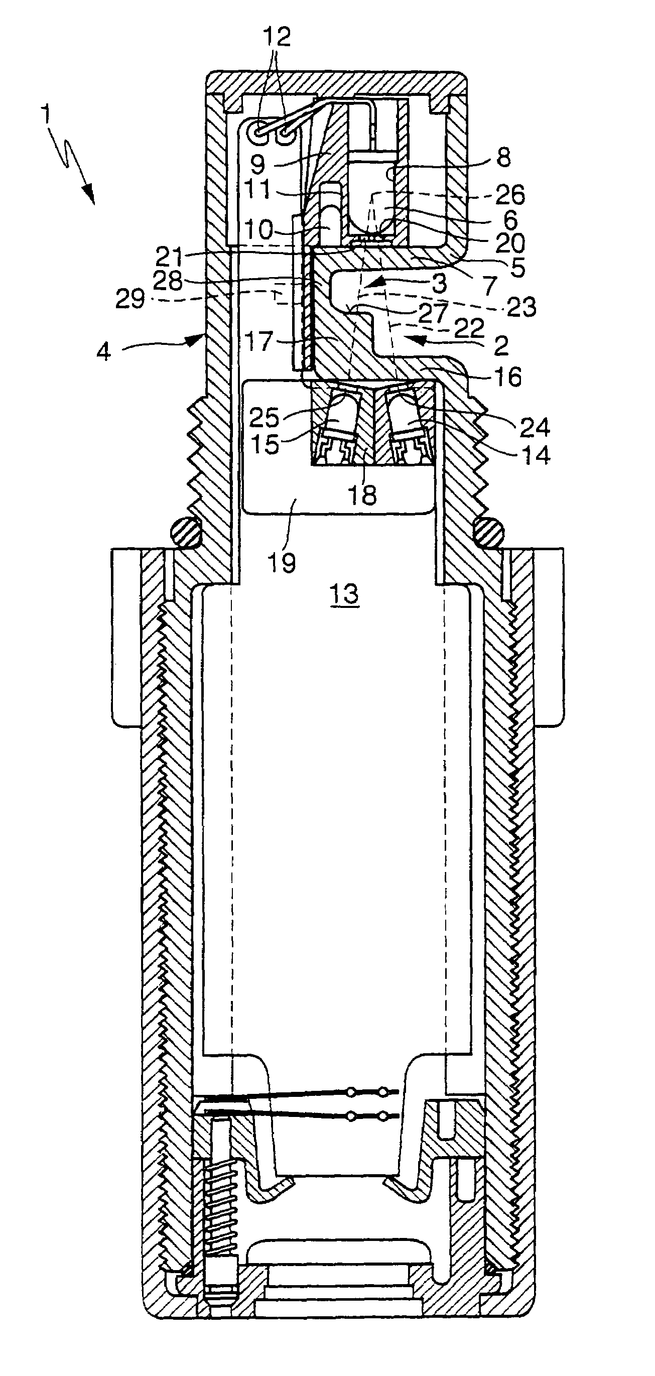
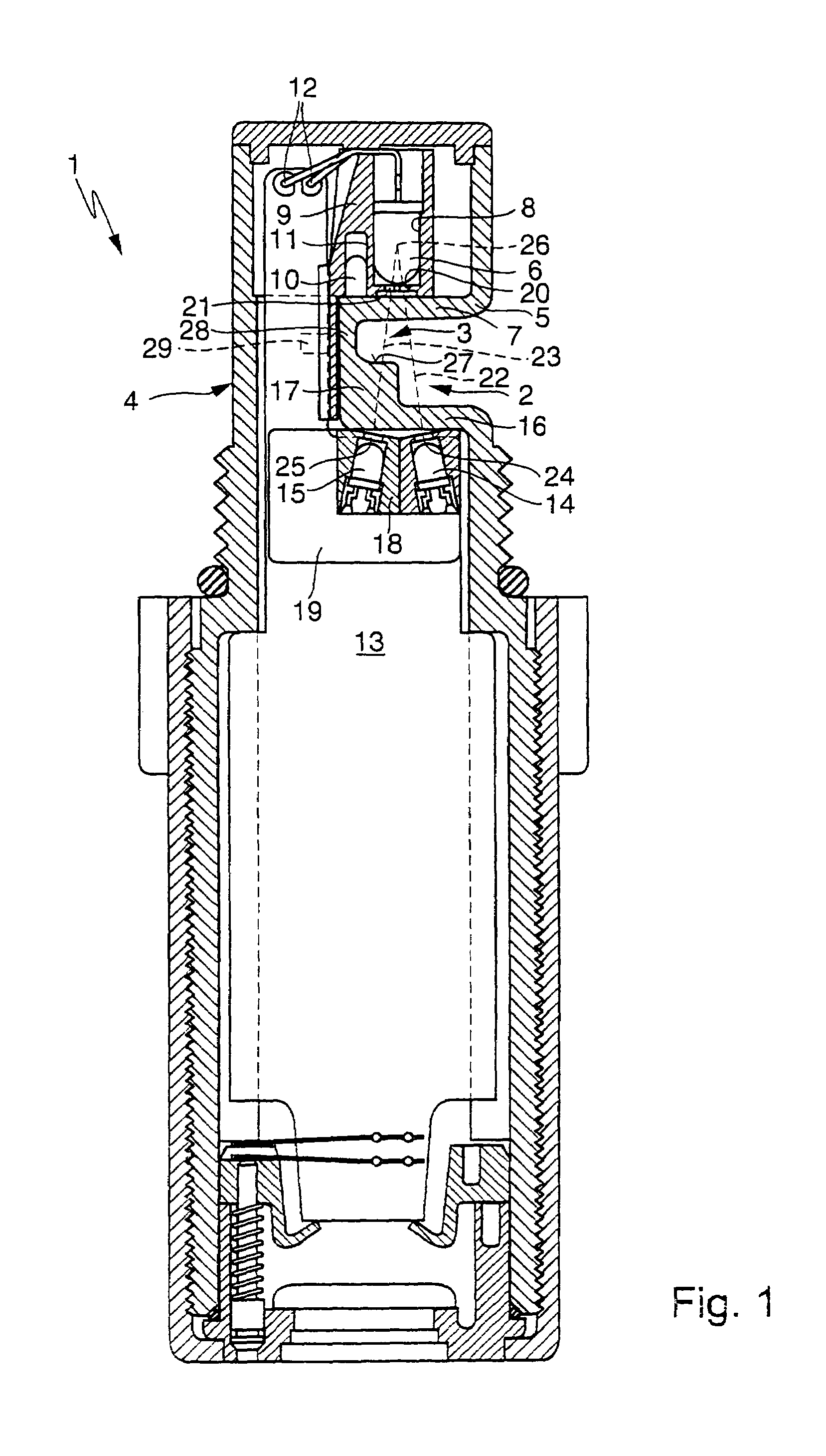
[0031]According to FIG. 1 an inventive transmission sensor 1 has a longer first measurement zone 2 and a shorter second measurement zone 3. During operation of the transmission sensor 1, the two measurement zones 2 and 3 are filled by a fluid (not shown here), e.g., a liquid or a gas which is to be monitored for impurities. The transmission sensor 1 has a housing 4, which has at least one wall 5 that is transparent for electromagnetic radiation, at least in the area of the measurement zones 2 and 3. This housing 4 is preferably manufactured as an injection molded part made of plastic.

[0032]A transmitter 6, e.g., in the form of a semiconductor element, is provided in the housing 4 close to an inlet area 7 in the wall 5. This transmitter 6 is capable of emitting electromagnetic radiation through the inlet area 7 into the measurement zones 2 and 3. The preferred electromagnetic radiation here is light, in particular infrared light. The transmitter 6 is mounted in a transmitter carrier ...


PUM

PropertyMeasurementUnit
temperatureaaaaaaaaaa
currentaaaaaaaaaa
turbidityaaaaaaaaaa

Abstract

The invention relates to a transmission sensor (1) for measuring the turbidity of a fluid, comprising a first and a second measuring section (2, 3). A transmitter (6) emits electromagnetic radiation into the two measuring sections (2, 3). A first receiver (14) is allocated to the first measuring section (2) and a second receiver (15) is allocated to the second measuring section (3). The transmitter (6) is inserted into a transmitter carrier (8) in such a way that the transmitter (6) is forced to adopt a predetermined oriented position. The receivers (14, 15) are inserted into a receiver carrier (18) in such a way that each of said receivers (14, 15) is forced to adopt a predetermined oriented position. A transmitter carrier holder (9) forcibly positions the transmitter carrier (8) in a predetermined location and a receiver carrier holder (19) forcibly positions the receiver carrier (18) in a predetermined location.

Description

CROSS REFERENCE TO RELATED APPLICATIONS[0001]Applicants claim priority under 35 U.S.C. §119 of German Application No. 101 19 932.5 filed on Apr. 23, 2001. Applicants also claim priority under 35 U.S.C. §365 of PCT / DE02 / 01465 filed on Apr. 22, 2002. The international application under PCT article 21(2) was not published in English.BACKGROUND OF THE INVENTION[0002]1. Field of the Invention[0003]This invention relates to a transmission sensor suitable for measuring turbidity of a fluid. This invention also relates to the use of such a transmission sensor and a method of operation using it.[0004]2. The Prior Art[0005]German Patent Application DE 199 57 592.4 of Nov. 30, 1999 discloses a transmission sensor having a lengthy first measurement zone and a shorter second measurement zone. The two measurement zones are filled with a fluid, the turbidity of which is to be measured during operation of the sensor. The known transmission sensor has a housing with a wall that is transparent for el...

Claims


Application Information

Patent Timeline
Patent Type & Authority Patents(United States)
IPC IPC(8): G01N21/05G01N21/53
CPCG01N21/532F16N2250/34
Inventor MANZ, ROLFSTEINER, GERHARDWIERLING, REINHARDSCHENKL, JOHANNBRABEC, MARTIN
Owner FILTRATION GRP GMBH
Why Eureka
Try Eureka