
Vehicle window molding

a technology for window molding and vehicles, applied in the field of vehicles, can solve the problems of vibration at the distal end of the seal lip, noise generation, undesirable noise, etc., and achieve the effect of convenient insertion, simple and positive fitting, and sufficient reliability

Active Publication Date: 2006-06-13
FALTEC CO LTD
View PDF7 Cites 22 Cited by
  • Summary
  • Abstract
  • Description
  • Claims
  • Application Information

AI Technical Summary

Benefits of technology

[0017]It is a primary object of the present invention to provide an improved vehicle window molding which eliminates or at least mitigates the above-mentioned problems of the prior art.

Problems solved by technology

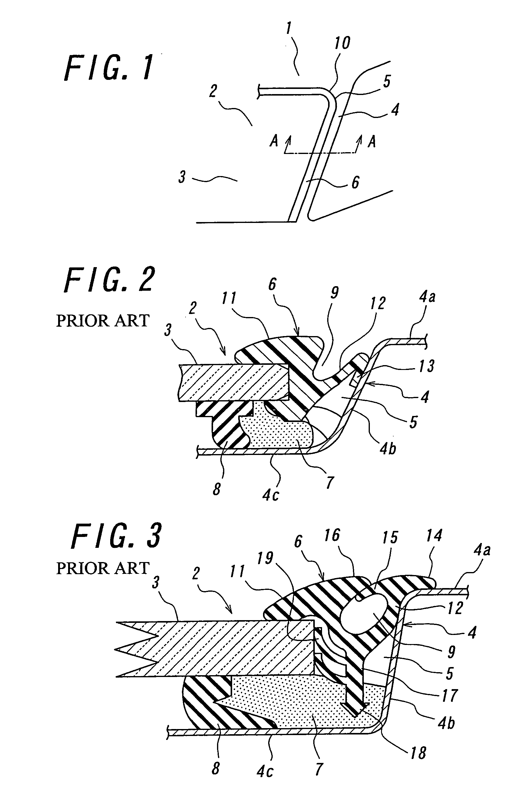
Thus, during high-speed running of the vehicle, exhausting draft is caused by a negative pressure to flow out of the gap 5 toward the rear side of the seal lip, causing the distal end of the seal lip to vibrate thereby generating undesirable noise.
Moreover, since the window molding 6 has a channel 9 in its outer surface, it is likely to cause noise generation.
Thus, not only the overall appearance deteriorates, but also exhausting draft flows outward the vehicle through the gap due to negative pressure during high-speed running of the vehicle, thereby possibly causing undesired noise generation.
However, since the first lip 14 extends to cover the outer surface 4a of the vehicle body panel 4, undesired noise tends to be generated due to vibration of the lip 14 during high-speed running of the vehicle, depending upon the configuration or structure of the lip 14.
In these cases, the second lip 15 is likely to vibrate, thereby generating undesired noise.

Method used


Image

  • Vehicle window molding
  • Vehicle window molding
  • Vehicle window molding

Examples


Embodiment Construction

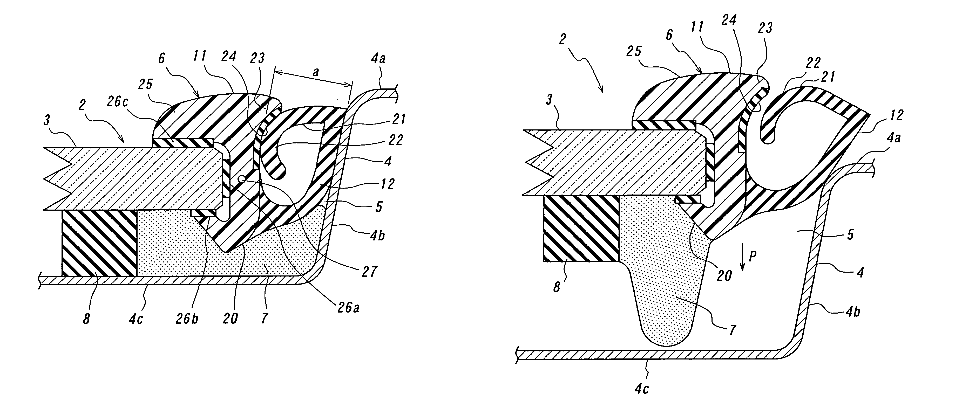
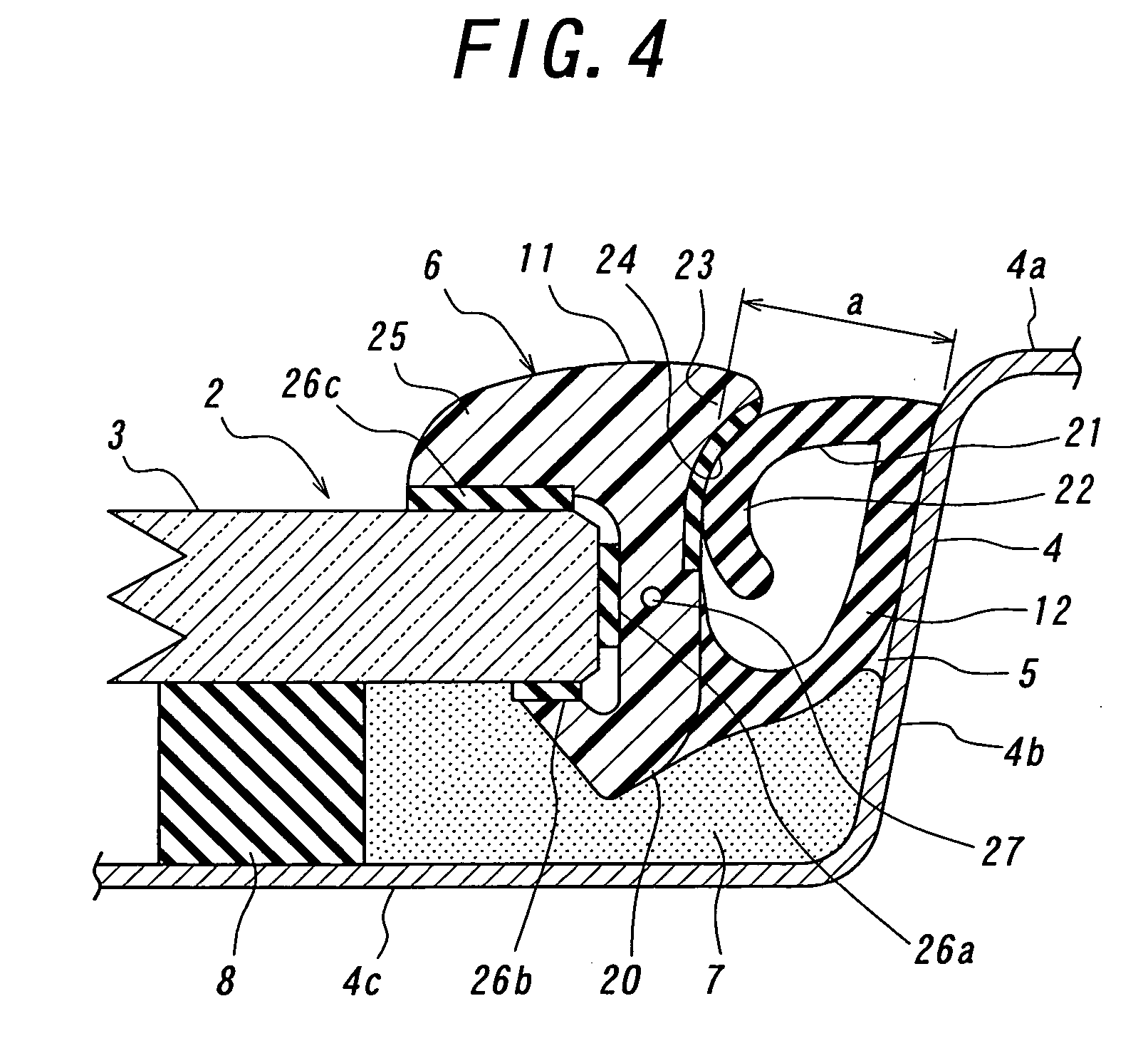
[0038]A vehicle window molding 6 according to a preferred embodiment of the present invention will be explained below with reference to FIGS. 4 and 5, which is illustrated as being for a front window, i.e., a windshield of a vehicle. The window molding 6 according to the present invention comprises a molding body 11 fitted so as to abut against the outer peripheral edge surface of a windowpane 3. An engaging member 20 extends from the molding body 11 so as to engage with the passenger compartment side of the windowpane 3. A seal lip 12 extends from the molding body 11 so as to abut against a stepped surface 4b of a vehicle body panel 4. A support lip 21 extends from that part of the seal lip 12 which abuts against the stepped surface, toward the molding body 11. An abutting member 22 is formed in the distal end part of the support lip 21 in a curved shape so as to press the molding body 11 in a slidable condition. A holding member 23 is provided for the molding body 11 so as to hold...


PUM


Abstract

A vehicle window molding for covering a gap between an outer peripheral edge surface of a vehicle windowpane and a vehicle body panel includes a molding body mounted in abutment against the outer peripheral end surface of the windowpane. An engaging member extends from the molding body to engage with the windowpane on the side of passenger compartment of the vehicle body. A seal lip extends from the molding body to abut against a stepped surface of the vehicle body panel. A support lip extends toward the molding body from a part of the seal lip where the seal lip abuts against said stepped surface. An abutting member is formed at a distal end part of the support lip to press the molding body in a slidable condition. A holding member has a holding surface that abuts against the support lip to hold the abutting member in a condition in which the molding is fitted to the vehicle body.

Description

BACKGROUND OF THE INVENTION[0001]1. Technical Field[0002]The present invention relates to a vehicle window molding that can be mounted between a vehicle windowpane and a vehicle body panel, for providing ornamental and sealing functions for the passenger compartment of vehicles.[0003]2. Related Art[0004]A typical structure of a vehicle window molding is explained below with reference to FIG. 1, which illustrates a vehicle body 1 and a window 2 in the form of a windshield. The window 2 includes a windowpane 3 that is mounted on a vehicle body panel 4 so as to leave a gap 5 between the outer periphery of the windowpane 3 and the vehicle body panel 4, which gap is covered by a window molding 6.[0005]Conventionally, the window molding 6 has a seal lip that extends from the molding body fitted in the gap 5, in order to cover part of the vehicle body panel 4 on the exterior side of the vehicle. The seal lip is made of a relatively soft material, such as soft resin or synthetic rubber, and...

Claims


Application Information

Patent Timeline
Patent Type & Authority Patents(United States)
IPC IPC(8): B60J10/02B60J1/02
CPCB60J10/0005B60J10/02B60J10/0088B60J10/16B60J10/45B60J10/70B60J1/02B60J1/18B60Y2200/11B60J10/50
Inventor MIKKAICHI, TOSHIKIOKANO, TOMOAKI
Owner FALTEC CO LTD
Learn More