
Stop control apparatus for internal combustion engine

a technology of control apparatus and internal combustion engine, which is applied in the direction of electrical control, hybrid vehicles, instruments, etc., can solve the problems of inapplicability of devices, and achieve the effects of reducing the starting energy preventing the deterioration of the battery, and improving the fuel consumption rate of the internal combustion engin

Inactive Publication Date: 2006-06-13
TOYOTA JIDOSHA KK
View PDF13 Cites 14 Cited by
  • Summary
  • Abstract
  • Description
  • Claims
  • Application Information

AI Technical Summary

Benefits of technology

[0015]In the case where a compression workload is controlled as mentioned above, the valve controlling device controls the operation of the valve mechanism so that the compression workload generated in the process of stopping the internal combustion engine is gradually reduced. In this case, since the compression pressure is gradually reduced according to decrease in the compression workload, vibration is suppressed and the internal combustion engine can be gently stopped.
[0018]When such a control is executed, the internal combustion engine is started from a state that the cylinder in which a compression workload is small is in the compression stroke. Starting energy of the internal combustion engine can be, therefore, reduced. As a result, the electric motor for starting the internal combustion engine is miniaturized, and the power consumption at the time of start is suppressed so that deterioration of the battery can be prevented and a fuel consumption rate of the internal combustion engine can be improved. The specified range of a cylinder of the plural cylinders, where a compression workload at the time of start is the least, may be preferentially determined, or the specified range may be determined with a cylinder where a compression workload at the time of start is the largest being avoided.

Problems solved by technology

Since the above-mentioned prior art, however, requires the motor generator in order to control a stop position, when the motor generator is not connected with the crankshaft of the internal combustion engine, this device is inapplicable.

Method used


Image

  • Stop control apparatus for internal combustion engine
  • Stop control apparatus for internal combustion engine
  • Stop control apparatus for internal combustion engine

Examples


first embodiment

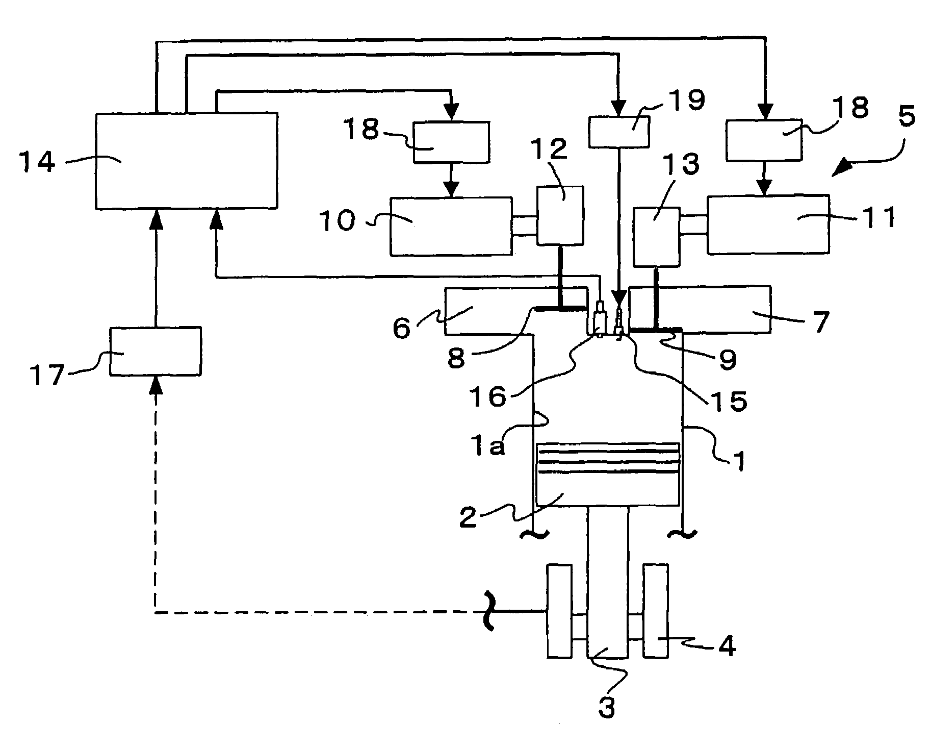
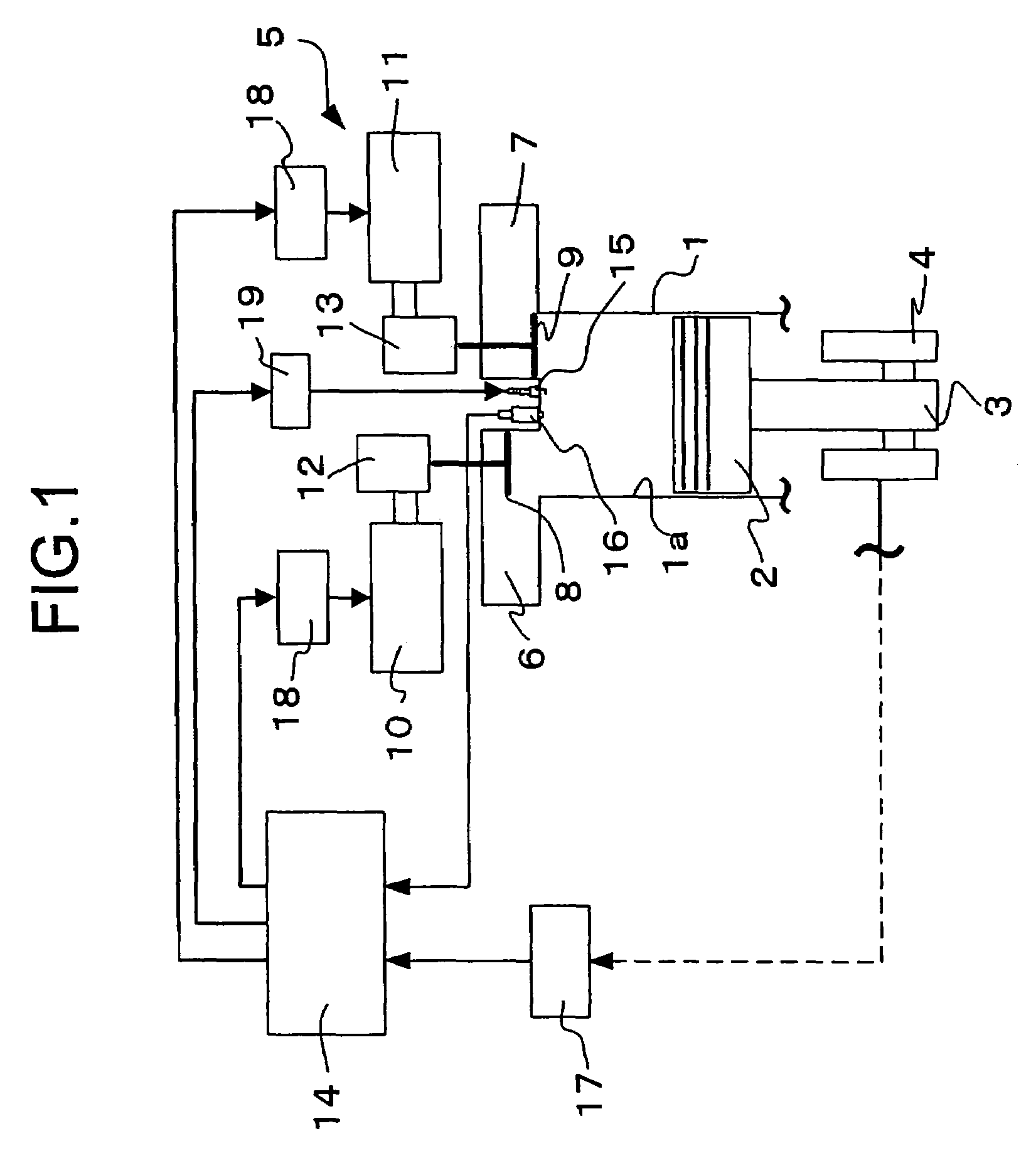
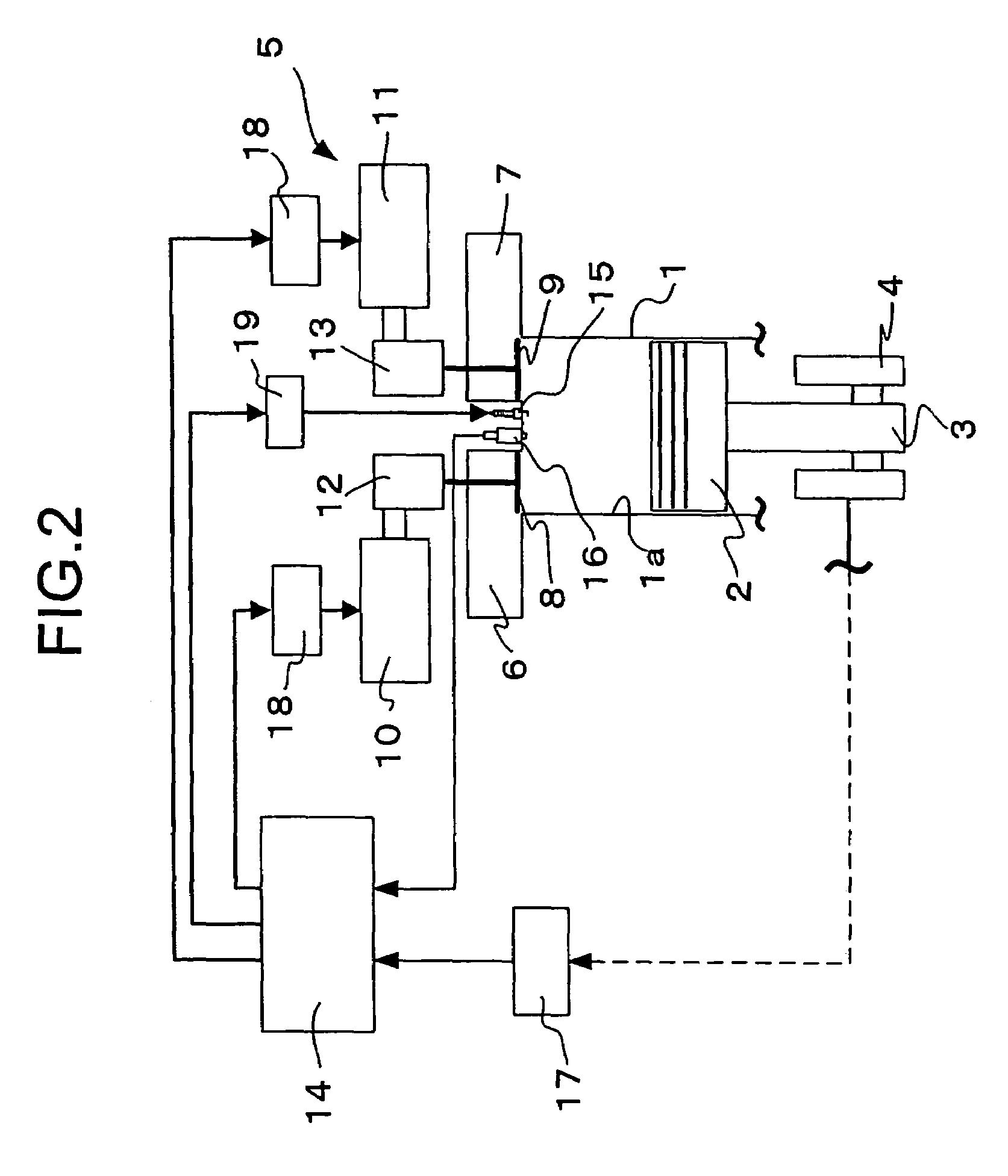
[0029]FIG. 1 illustrates a stop control apparatus according to a first embodiment of the present invention and an internal combustion engine to which the stop control apparatus is applied. An internal combustion engine 1 is constituted as a four-cycle gasoline engine which is mounted to a vehicle as a power source for traveling. The vehicle mounted with the internal combustion engine 1 is provided with a motor generator (not shown) as another power source for traveling. Such a vehicle is known as a so-called hybrid vehicle. In the hybrid vehicle, the internal combustion engine 1 and the motor generator are used appropriately according to suitable control rules, but in the present embodiment, operations of the internal combustion engine 1 and the motor generator are controlled at least in the following manner.

[0030]For the operation of the internal combustion engine 1, a stop permission condition is set in connection with an operating condition, and when the stop permission condition...

second embodiment

[0042]A second embodiment of the present invention is characterized in that at the stop process of the internal combustion engine 1 in the hybrid vehicle shown in FIG. 1, the ECU 14 controls the opening and closing operation of the intake valve 8 and the exhaust valve 9 of one specific cylinder (hereinafter, specific cylinder) 1a so as to stop the crankshaft 4 at a predetermined crank angle. FIG. 4 shows a procedure of a valve control routine at the time of stop executed by the ECU 14 in order to realize the control of the stop. The valve control routine at the time of stop is executed only at the stop process for the internal combustion engine 1. The routine in FIG. 4, for example, is started at suitable time after the stop permission condition is satisfied and is continued until the internal combustion engine 1 is completely stopped.

[0043]At the routine in FIG. 4, the ECU 14 opens the inlet vales 8 and the exhaust valves 9 of all the cylinders 1a other than the specific cylinder 1...

third embodiment

[0049]A third embodiment of the present invention is characterized in that a quantity of the compression work generated in the specific cylinder in the second embodiment is gradually reduced, and the crankshaft 4 is stopped at a predetermined crank angle. FIG. 7 shows a procedure of a valve characteristic setting routine at the time of stop executed by the ECU 14 in order to realize the stop control. The routine in FIG. 7 is executed in parallel with the valve control routine at the time of stop only while the process for stopping the internal combustion engine 1.

[0050]In the routine in FIG. 7, the ECU 14 specifies the operating state of the internal combustion engine 1 at step s31. The operating state can be specified by various parameters correlative with the operating state at the process for stopping the internal combustion engine 1. The parameters include a number of revolution of the combustion engine specified based on the crank angle detected by the crank angle sensor 17, an...


PUM


Abstract

A stop control apparatus for an internal combustion engine is provided with a valve mechanism capable of operating at least one of an intake valve and an exhaust valve independently a crankshaft of an internal combustion engine, and a valve controlling device for controlling an operation of the valve mechanism so that the internal combustion engine is stopped in a predetermined state.

Description

BACKGROUND OF THE INVENTION[0001]1. Field of the Invention[0002]The present invention relates to an apparatus for controlling an operation of an intake valve or an exhaust valve of an internal combustion engine so as to stop the internal combustion engine in a predetermined state.[0003]2. Description of the Related Art[0004]In order to improve startability of an internal combustion engine, there is suggested an apparatus for operating a motor generator when an internal combustion engine is being stopped, and braking or driving a crankshaft of the internal combustion engine so as to stop the crankshaft thereof at a predetermined angle (see Japanese Patent Application Laid-Open No. HEI9-264235).[0005]Since the above-mentioned prior art, however, requires the motor generator in order to control a stop position, when the motor generator is not connected with the crankshaft of the internal combustion engine, this device is inapplicable. Even when the motor generator is provided, it is ne...

Claims


Application Information

Patent Timeline
IPC IPC(8): F02D29/00F01L31/00B60L50/15F02N11/04F02D13/00F02D13/02F02D13/06F02D13/08F02D17/00F02D17/04F02D29/02F02D41/04F02D41/34F02D45/00F02N11/08F02N19/00
CPCF02D13/08F02D17/04F02D41/042F02N19/005B60K6/48F02D41/009Y02T10/18F02D2041/0095F02N19/004F02N2019/008Y02T10/6221F02D2041/001B60L2240/441Y02T10/12Y02T10/62
Inventor KATAOKA, KENJIASADA, TOSHIAKIEZAKI, SHUICHITSUJI, KIMITOSHIKUSAKA, YASUSHI
Owner TOYOTA JIDOSHA KK
Learn More