
Wireless terminal operating under an aggregate transmit power limit using multiple modems having fixed individual transmit power limits

a wireless terminal and aggregate technology, applied in power amplifiers, power management, electrical equipment, etc., can solve the problems of unacceptable operating transmit power limits of power amplifiers, undesired rf output signals, unacceptable out-of-band rf emissions, etc., to achieve the effect of maximizing the overall communication bandwidth

Active Publication Date: 2006-06-06
QUALCOMM INC
View PDF9 Cites 28 Cited by
  • Summary
  • Abstract
  • Description
  • Claims
  • Application Information

AI Technical Summary

Benefits of technology

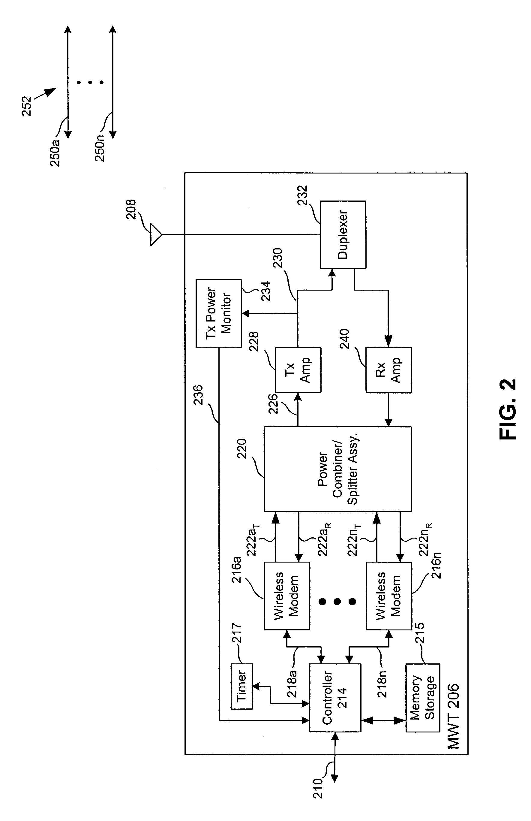
The present invention provides an MWT that maximizes communication bandwidth in both the reverse and forward link directions using multiple concurrently operating communication links, each associated with a respective one of a plurality of modulator-demodulators. The invention also combines multiple modulator-demodulator transmit signals into an aggregate transmit signal, reducing power consumption, cost, and space requirements compared to known systems using multiple power amplifiers. The invention carefully controls the aggregate input and output power of the transmit power amplifier to avoid signal distortion at the amplifier output. The invention detects and deactivates "over-limit" modems that have an actual transmit power or required transmit power that exceeds the transmit power limit in the modem. The deactivated modems are then reactivated when appropriate to reduce the overall adverse impact to reverse link through-put that may be caused by their initial deactivation.

Problems solved by technology

An inordinately high input power may over-drive the power amplifier, and thus cause the output power to exceed an acceptable operating transmit power limit of the power amplifier.
In turn, this may cause undesired distortion of the RF output signal, including unacceptable out-of-band RF emissions.

Method used


Image

  • Wireless terminal operating under an aggregate transmit power limit using multiple modems having fixed individual transmit power limits
  • Wireless terminal operating under an aggregate transmit power limit using multiple modems having fixed individual transmit power limits
  • Wireless terminal operating under an aggregate transmit power limit using multiple modems having fixed individual transmit power limits

Examples


Embodiment Construction

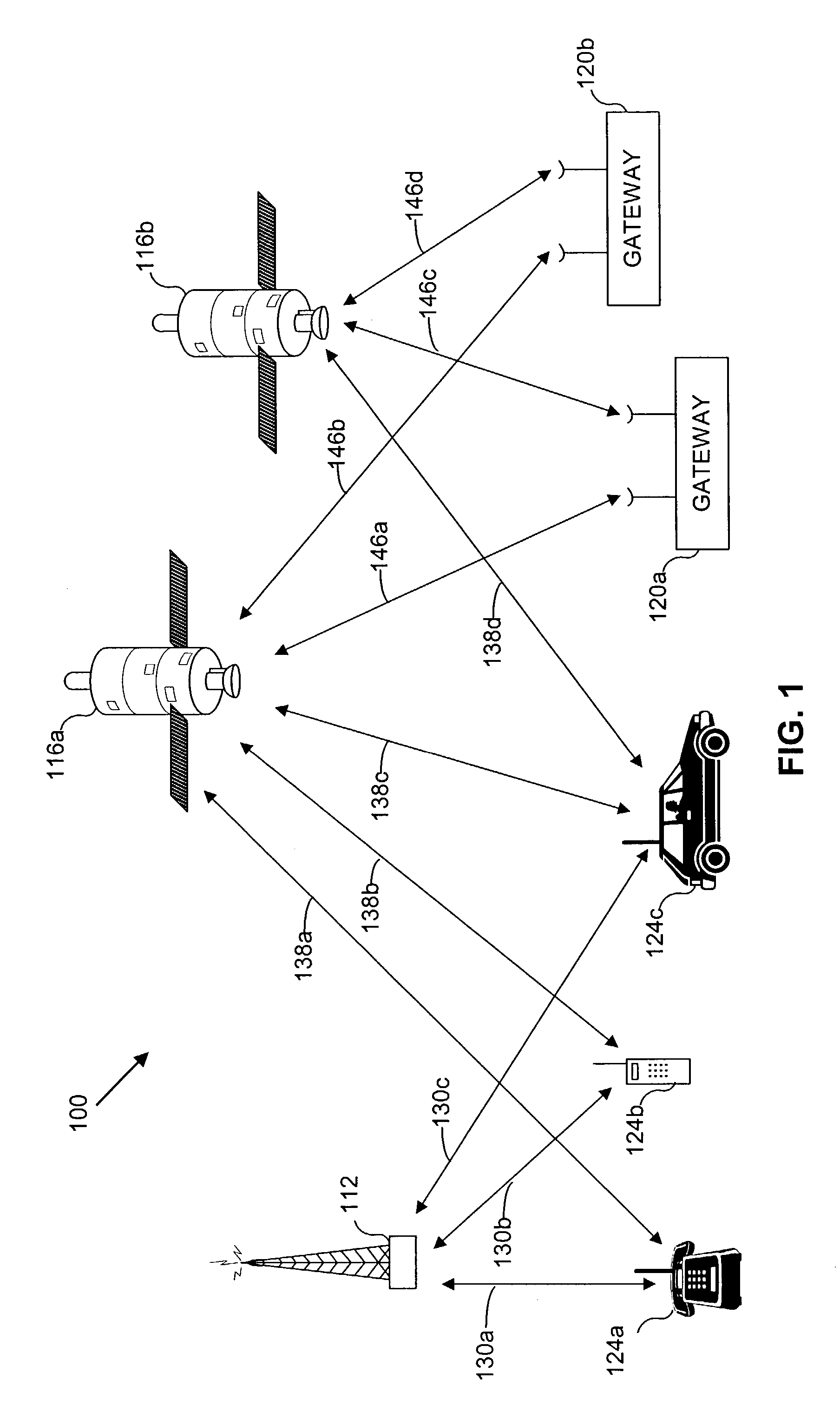
[0028]A variety of multiple access communication systems and techniques have been developed for transferring information among a large number of system users. However, spread spectrum modulation techniques, such as those used in code division multiple access (CDMA) communication systems provide significant advantages over other modulation schemes, especially when providing service for a large number of communication system users. Such techniques are disclosed in the teachings of U.S. Pat. No. 4,901,307, which issued Feb. 13, 1990 under the title “Spread Spectrum Multiple Access Communication System Using Satellite Or Terrestrial Repeaters,” and U.S. Pat. No. 5,691,174, which issued Nov. 25, 1997, entitled “Method and Apparatus for Using Full Spectrum Transmitted Power in a Spread Spectrum Communication System for Tracking Individual Recipient Phase Time and Energy,” both of which are assigned to the assignee of the present invention, and are incorporated herein by reference in their...


PUM


Abstract

A mobile wireless terminal (MWT) includes multiple wireless modems. The multiple modems have their respective transmit outputs combined to produce an aggregate transmit output. The multiple modems can concurrently transmit data in a reverse link direction and receive data in a forward link direction. The MWT is constrained to operate under an aggregate transmit power limit. Each of the multiple modems has an individual transmit limit related to the aggregate transmit power limit. When operating, over-limit ones of the multiple modems are deactivated and then reactivated to keep an aggregate transmit power of all of the modems below the aggregate limit, and to maximize data through-put on the forward and reverse links.

Description

[0001]This application is related to commonly-owned applications, filed concurrently herewith, entitled “Controlling Multiple Modems In A Wireless Terminal Using Energy-Per-Bit Determinations” having application Ser. No. 10 / 283,935, filed Oct. 29, 2002, now allowed, and “Controlling Multiple Modems In A Wireless Terminal Using Dynamically Varying Modem Transmit Power Limits” having application Ser. No. 10 / 283,934, filed Oct. 29, 2002, now allowed, which are incorporated herein by reference.BACKGROUND OF THE INVENTION[0002]I. Field of the Invention[0003]The present invention relates generally to mobile wireless terminals, and particularly, to mobile wireless terminals having multiple modems which are constrained to operate under an aggregate transmit power limit for all of the modems.[0004]II. Related Art[0005]In a data call established between a mobile wireless terminal (MWT) and a remote station, the MWT can transmit data to the remote station over a “reverse” communication link. A...

Claims


Application Information

Patent Timeline
Patent Type & Authority Patents(United States)
IPC IPC(8): H04B7/00H04B7/005
CPCH04W52/30H04W52/34H04W52/52H04W52/42H04W52/36
Inventor NGAI, FRANCIS M.GHOLMIEH, AZIZGERECHT, DOUGANDERSON, JON J.PANTON, WILLIAM R.
Owner QUALCOMM INC
Learn More