Laparoscopic direct vision dissecting port

Inactive Publication Date: 2006-06-06
INTELLIMED SURGICAL SOLUTIONS
View PDF32 Cites 94 Cited by
  • Summary
  • Abstract
  • Description
  • Claims
  • Application Information

AI Technical Summary

Benefits of technology

[0018]Disposed within the tubular housing of the laparoscopic port is an inner actuator sleeve operatively coupled to a handle mechanism extending from the proximal end of the tubular housing that selectively extends distally within the laparoscopic port when the handle mechanism is actuated to thus cause the distal end of the port to selectively transition between its closed and operative configurations. In this respect, as the actuator sleeve is advanced inwardly toward the closed distal end of the port, the forward axial movement of the actuator causes the flaps of the distal end to extend radially outward, thus causing the tissue surrounding the distal end to selectively spread apart as the distal-most end of the device is advanced into the peritoneal cavity. To help achieve that end, the flaps may be formed to have a gradually increasing wall thickness toward the distal ends thereof to thus enable the same to more readily spread apart as the actuator sleeve is advanced toward the closed distal end of the port.
[0026]Still further objects of the present invention are to provide a laparoscopic direct vision dissecting port that, in addition to substantially minimizing the risk of internal organ injury, is of simple construction, easy to use, relatively inexpensive to manufacture, and can be readily deployed utilizing conventional laparoscopic surgical devices and related techniques.

Problems solved by technology

Despite its advantages, laparoscopic surgery as currently performed can pose substantial risks to the patient.
In this respect, it is widely recognized that entry into the peritoneal cavity during laparoscopic surgery, due to the procedure by which the peritoneal cavity is accessed, can cause serious injury to the abdominal organs, such as the spleen, liver and intestine as well as surrounding blood vessels.
This risk is due in large part to the fact that in the unoperated abdomen, most surgeons enter the peritoneal cavity using a Veress needle, which is pushed blindly through the patient's fascia and peritoneum.
Problematic with such procedure, however, is the fact that the abdomen is entered blindly on two separate occasions, first through the introduction of the Veress needle and second through the laparoscopic port, which can and frequently does injure abdominal organs and surrounding blood vessels.
In this regard, it is known that when a patient has undergone previous abdominal surgery, the abdominal contents can become adherent to the abdominal wall, making blind placement of a Veress needle or trocar too risky of a technique.
Such alternative procedure, however, typically requires a larger skin incision than is typically produced via the use of the Veress needle technique, particularly with respect to obese patients, and is further more prone to gas leakage during surgery, thus requiring constant monitoring and maintenance of adequate insufflation.
Such device, however, does not allow for any type of spreading of the cut tissue to enable the surgeon to see the next layer of tissue to be entered.
In fact, inadvertent entry into an organ cannot be avoided via use of such device, and it is only after the organ is entered (and hence damaged) that such matter can be appraised.
Moreover, the use of clear plastic has substandard optical visualization due to optical properties inherent in such material, coupled with the conical shape, such that advancement of the tip fails to provide a clear visualization as the same is advanced through tissue.
While the cone-shaped distal end is operative to move tissue away such that visualization of tissues and the like can be enhanced, such cone-shaped distal end does not provide any dissection function.
Indeed, the flaps of the distal end of the cone member are flimsy in nature and non-reinforced.
As such, the same are ill suited for enhancing direct visualization, much less providing any type of dissecting function.
Such device is further not designed for use in laparoscopic applications, and in particular a laparoscopic port through which other instruments can be positioned and deployed.

Method used


Image

  • Laparoscopic direct vision dissecting port
  • Laparoscopic direct vision dissecting port
  • Laparoscopic direct vision dissecting port

Examples


Embodiment Construction

[0038]The detailed description set forth below is intended as a description of the presently preferred embodiment of the invention, and is not intended to represent the only form in which the present invention may be constructed or utilized. The description sets forth the functions and sequences of steps for constructing and operating the invention. It is to be understood however, that the same or equivalent functions and sequences may be accomplished by different embodiments and that they are also intended to be encompassed within the scope of the invention.

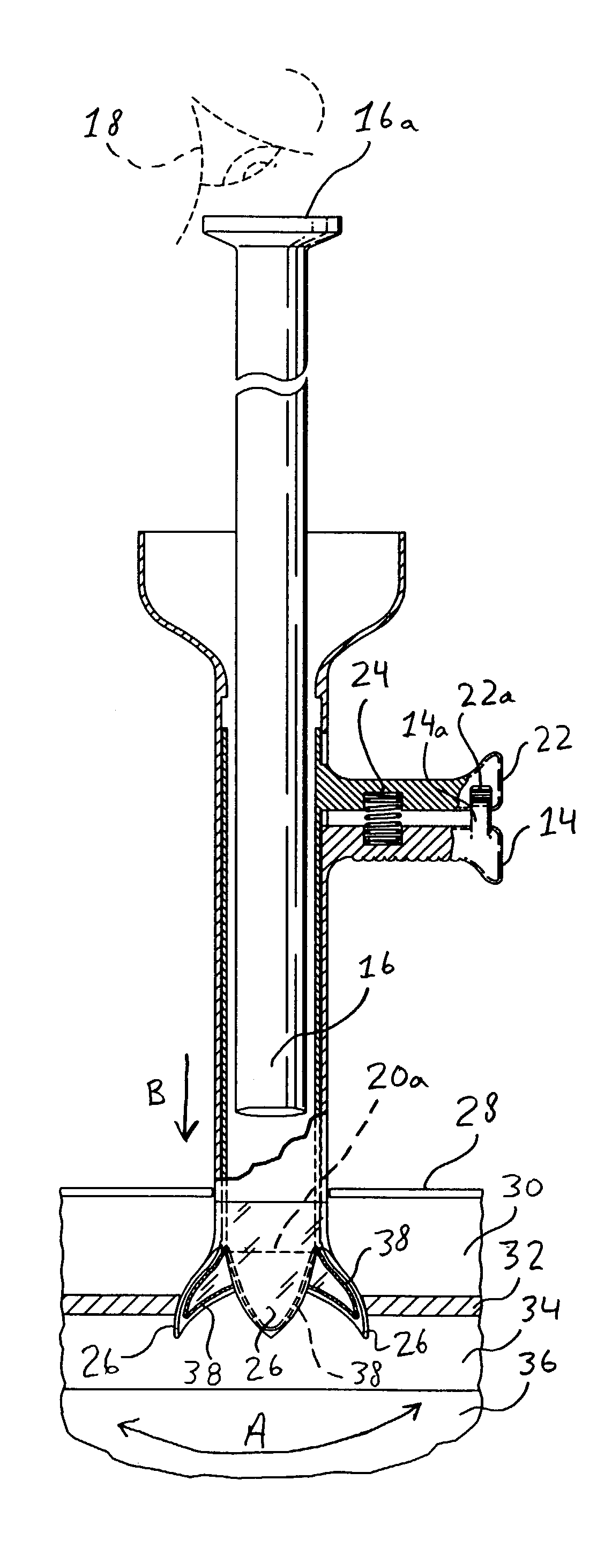
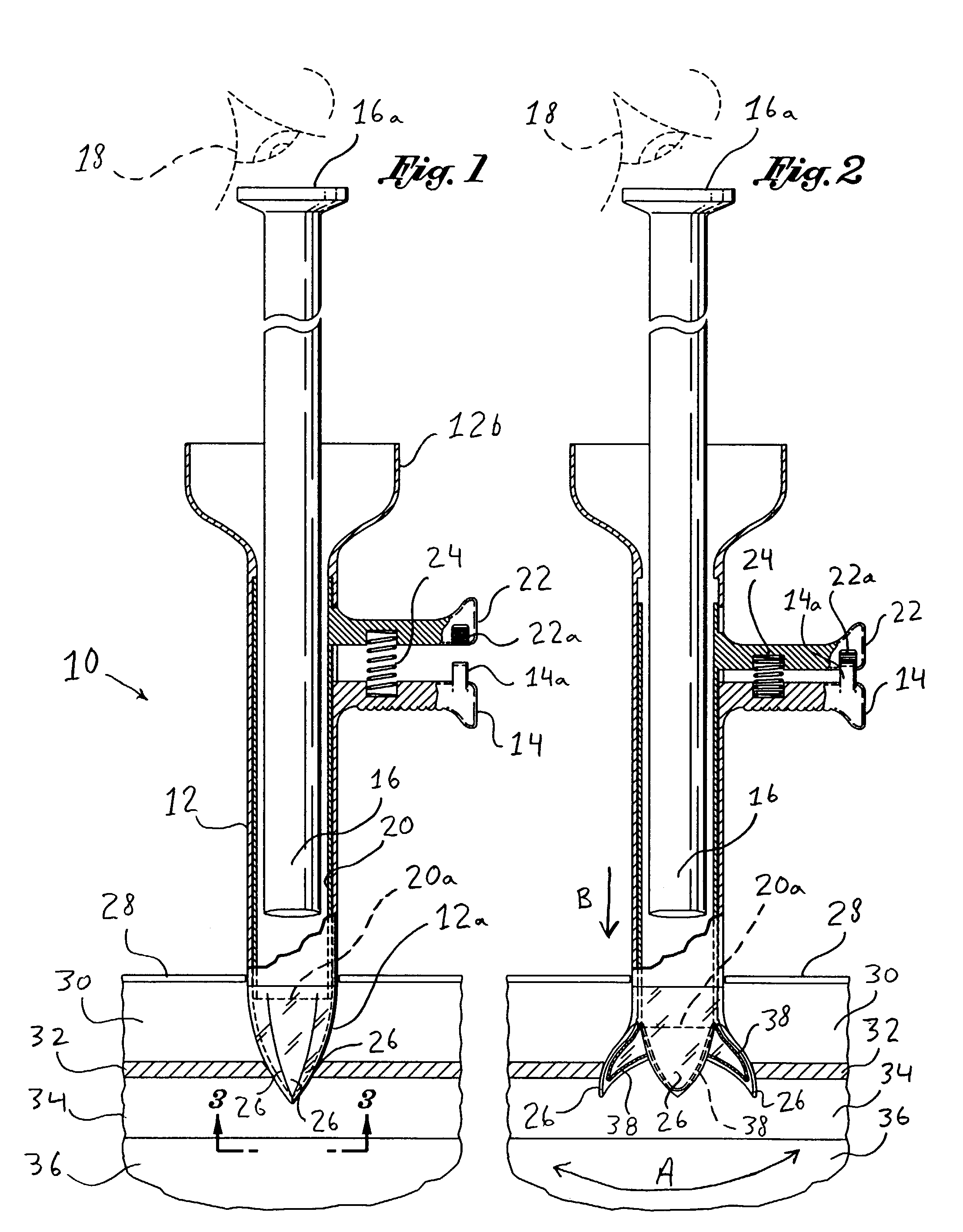
[0039]Referring now to the drawings, and initially to FIG. 1, there is shown a cross sectional view of a laparoscopic direct vision dissecting port 10 constructed in accordance with a preferred embodiment of the present invention. As illustrated, the port 10 comprises an elongate tubular housing 12 having a transparent or non-opaque distal end 12a operative to be inserted within an incision formed upon the skin 28 of a patient a...


PUM


Abstract

A laparoscopic direct vision dissecting port for providing safe entry into a body cavity, as well as being operative to serve as a standard laparoscopic port for use in laparoscopic surgery. The device comprises an elongate laparoscopic port within which a laparoscope may be positioned. The distal-most end of the tip is transparent in nature and operatively transitional between a closed configuration and an open, operative configuration, the latter of which causing tissue to be selectively dissected in a layer-by-layer fashion while under the direct vision of the laparoscope disposed therein. The port may further optionally assume an anchor configuration once positioned within the patient to enable the same to remain securely in position during the laparoscopic surgical procedure.

Description

CROSS-REFERENCE TO RELATED APPLICATIONS[0001](Not Applicable)STATEMENT RE: FEDERALLY SPONSORED RESEARCH / DEVELOPMENT[0002](Not Applicable)BACKGROUND OF THE INVENTION[0003]Laparoscopic surgery is a well-known, widely utilized surgical technique that advantageously reduces patient recovery time due to its minimal tissue damage. Generally, laparoscopic surgery relies upon the formation of one or more puncture wounds through which a body cavity, typically the peritoneal cavity, can be accessed. In this regard, once the peritoneal cavity has been entered, the same is insufflated with carbon dioxide gas, typically to a pressure of approximately 15 mm Hg, followed by the introduction of a laparoscopic port with trocar, which may either be bladed or blunt.[0004]The laparoscopic port is put into the peritoneal cavity followed by the placement of a laparoscope therethrough to thus provide visualization of the cavity thus enabling the surgeon to view the surrounding organs and conduct the surgi...

Claims


Application Information

Patent Timeline
IPC IPC(8): A61B17/28A61B1/313A61B17/02A61B17/34A61B19/00
CPCA61B17/3421A61B1/313A61B17/0218A61B2019/5231A61B19/5212A61B2017/3484A61B2090/373A61B90/361A61B17/0206A61B17/3417A61B17/3439A61B17/3496
Inventor KERR, STEPHEN
Owner INTELLIMED SURGICAL SOLUTIONS
Why Eureka
Try Eureka