Method and apparatus for error reduction in an orthogonal modulation system

a modulation system and orthogonal technology, applied in orthogonal multiplex, multiplex communication, baseband system details, etc., can solve the problems of reducing spectral efficiency, reducing bandwidth availability, and using a guard band interval or cyclic prefix, so as to reduce the error of a transmitted signal

Inactive Publication Date: 2006-05-30
NOKIA CORP
View PDF18 Cites 44 Cited by
  • Summary
  • Abstract
  • Description
  • Claims
  • Application Information

AI Technical Summary

Benefits of technology

[0011]The present invention overcomes many of the foregoing problems and / or disadvantages by providing a method and apparatus that can reduce error in a transmitted signal and maintain a symbol error rate at an acceptable level under conditions of excessive multipath delay. The invention is particularly useful in wireless communication systems having multiple communication devices that each utilizes an orthogonal modulation scheme. In one embodiment, the invention includes a communication device of the multiple communication devices having a receiver that receives a signal that includes multiple orthogonal subcarriers. A signal processing unit coupled to the receiver determines a signal quality metric for each subcarrier of the multiple orthogonal subcarriers and determines subcarrier suppression information based on the determined signal quality metrics. A transmitter coupled to the signal processing unit then transmits the subcarrier suppression information. The subcarrier suppression information can be used by a second communication device of the multiple communication devices to suppress one or more orthogonal subcarriers of multiple orthogonal subcarriers included in a signal transmitted by the second communication device, thereby reducing the signal distortion and splatter that may be introduced to the transmitted signal by the suppressed subcarriers.
[0012]In an alternative embodiment of the present invention, wherein a communication channel introduces multipath delay to a transmitted signal, the invention includes a communication device having a receiver coupled to a signal processing unit. The receiver receives a signal comprising multiple orthogonal subcarriers. The signal processing unit determines a transfer function corresponding to the communication channel, determines an equalization function that is based on the determined communication channel transfer function, and processes the signal based on the determined equalization function. The equalization function reduces the multipath when the multipath delay exceeds a tolerable multipath delay, thereby reducing error in the received signal.
[0014]In still another alternative embodiment of the present invention, wherein a transmitted signal comprises multiple orthogonal subcarriers, the invention combines the use of subcarrier suppression information and an equalization function in order to reduce error in a transmitted signal. A first communication device of multiple communication devices suppresses an orthogonal subcarrier of multiple orthogonal subcarriers based on the subcarrier suppression information to produce transmitted signal that includes suppressed and non-suppressed subcarriers. A second communication device receives the transmitted signal, determines an equalization function that reduces a multipath delay of the received signal, and processes the received signal based on the determined equalization function.

Problems solved by technology

The limited availability of bandwidth is a critical constraint on the capacity of wireless communication systems.
Use of a guard band interval, or cyclic prefix, reduces spectral efficiency since time is consumed repeating part of the information.
In wireless communication systems, multipath delay can be very unpredictable.
Excessive multipath delay in an OFDM system causes a loss of orthogonality among the subcarriers and causes interference among consecutive symbols transmitted in a sub-band, producing an irreducible and unacceptably high error floor, that is, a minimum symbol error rate that cannot be reduced even in a very high signal-to-noise ratio communication.

Method used


Image

  • Method and apparatus for error reduction in an orthogonal modulation system
  • Method and apparatus for error reduction in an orthogonal modulation system
  • Method and apparatus for error reduction in an orthogonal modulation system

Examples


Embodiment Construction

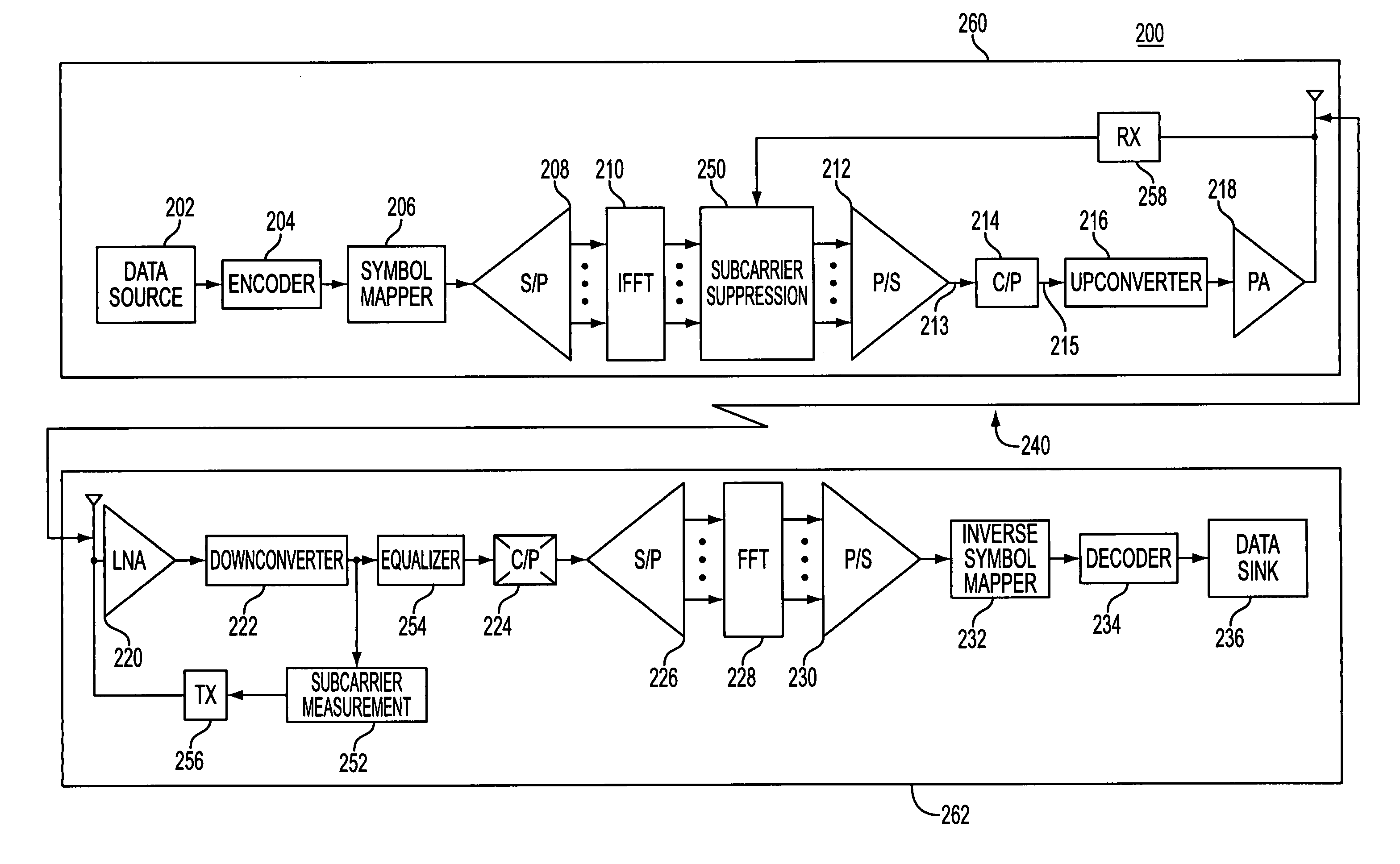
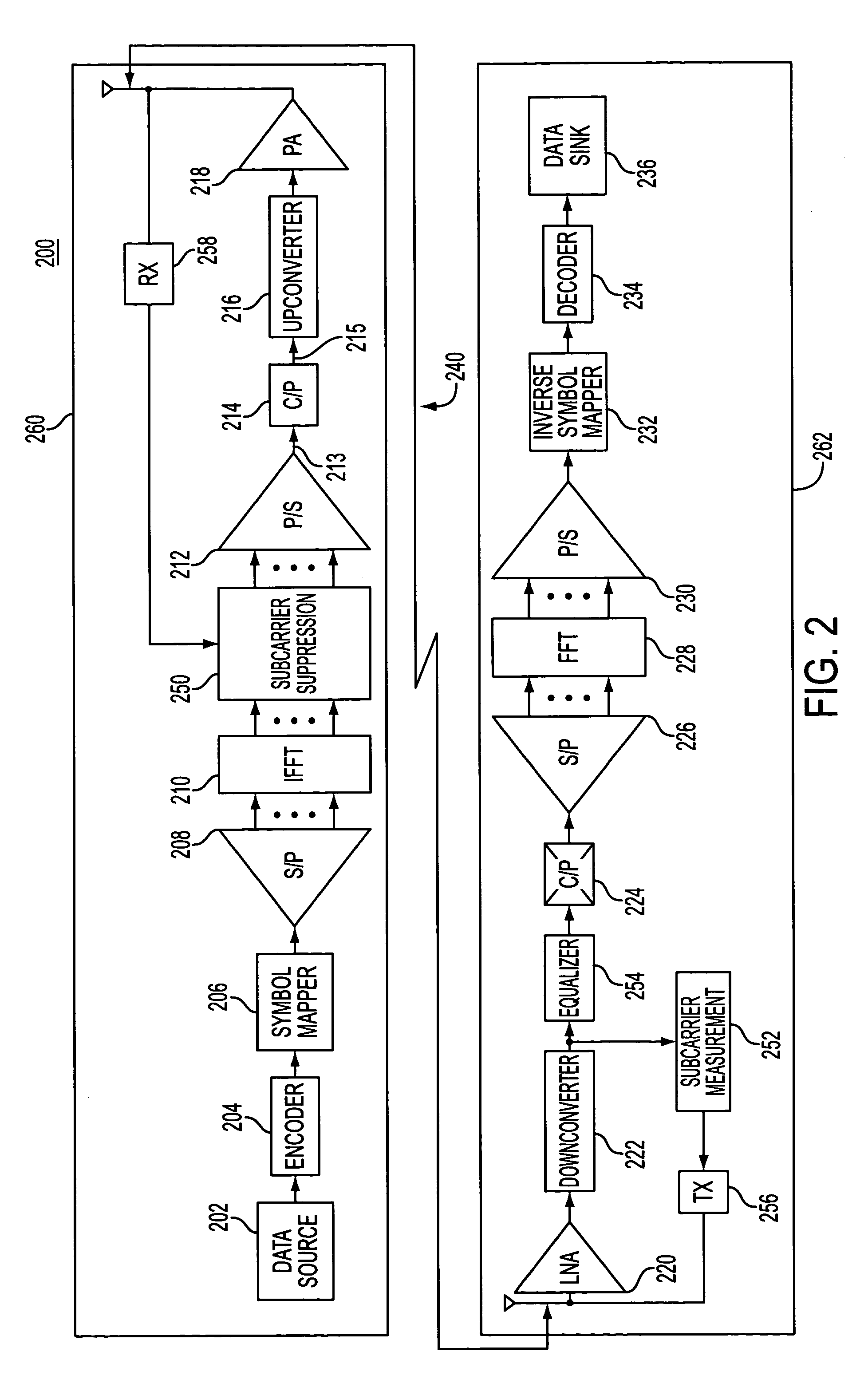
[0025]The present invention may be more fully described with reference to FIGS. 2–10. FIG. 2 is a block diagram of a communication system 200 in accordance with an embodiment of the present invention. Communication system 200 includes a transmit side 260 and a receive side 262, as shown. Communication system 200 may be, for example, a cellular telephone system in which the transmit side 260 is embodied within a cell phone or other type of subscriber radio unit, and the receive side 262 is embodied within a base station or other fixed receiving equipment, or vice versa. Further still, transmit side 260 and receive side 262 may be embodied within separate subscriber units, respectively, or within separate base stations, respectively. Of course, the present invention may be beneficially applied to other types of communication systems, particularly wireless communication systems.

[0026]FIG. 3 is a block diagram of a communication device 300 capable of operating in communication system 20...


PUM


Abstract

A method and apparatus reduces error in a communication system that includes multiple orthogonal subcarriers by suppressing a subcarrier in a transmitting communication device and by equalizing a received signal in a receiving communication device. Subcarrier suppression is based on a determination of a signal quality metric with respect to each subcarrier or is based on a determination of excessive signal power overdriving an amplifier of the receiving communication device. Equalization of the received signal is based on an equalization function that reduces a multipath delay introduced to the transmitted signal when the multipath delay exceeds a tolerable multipath delay.

Description

TECHNICAL FIELD[0001]The present invention relates generally to wireless communication systems and, in particular, to the use of orthogonal modulation schemes to code information in a wireless communication system.BACKGROUND OF THE INVENTION[0002]The limited availability of bandwidth is a critical constraint on the capacity of wireless communication systems. To enhance capacity, orthogonal modulation schemes, such as Orthogonal Frequency Division Multiplexing (OFDM), have been developed for the modulation of information onto a carrier and subsequent transmission of the modulated signal.[0003]OFDM is a wideband modulation scheme that divides a frequency bandwidth allocated for a communication session into multiple narrower frequency sub-bands. Each sub-band includes a radio frequency (RF) subcarrier, wherein each subcarrier is mathematically orthogonal to the RF subcarrier included in each of the other subchannels. The orthogonality of the subcarriers allows their individual spectra ...

Claims


Application Information

Patent Timeline
IPC IPC(8): H04K1/10H04J11/00H04B7/005H04L1/20H04L25/03H04L27/26
CPCH04L1/0025H04L5/0044H04L5/006H04L5/0007H04L2025/03414H04L5/0023H04L27/26
Inventor KANNAN, ANANDKADOUS, TAMER
Owner NOKIA CORP
Why Eureka
Try Eureka