Constant voltage generating circuit and reference voltage generating circuit

a constant voltage generation and reference voltage technology, applied in amplifiers, instruments, amplifiers with semiconductor devices/discharge tubes, etc., can solve the problems of substrate area and associated costs, increase in substrate area, and decrease in battery life, so as to suppress the variation of the input power source voltage to the band-gap circuit, and suppress the band-gap reference voltage

Active Publication Date: 2006-05-30
DENSO CORP
View PDF5 Cites 17 Cited by
  • Summary
  • Abstract
  • Description
  • Claims
  • Application Information

AI Technical Summary

Benefits of technology

[0009]The present invention has been implemented in view of the foregoing description, and has an object to provide a reference voltage generating circuit which can reduce operating current and also suppress variation of a band-gap reference voltage due to variation of an input power source voltage.

Problems solved by technology

The increase in current consumption causes a decrease in the battery lifetime.
However, the addition of a capacitor causes an increase in substrate area and associated costs.

Method used


Image

  • Constant voltage generating circuit and reference voltage generating circuit
  • Constant voltage generating circuit and reference voltage generating circuit
  • Constant voltage generating circuit and reference voltage generating circuit

Examples


Embodiment Construction

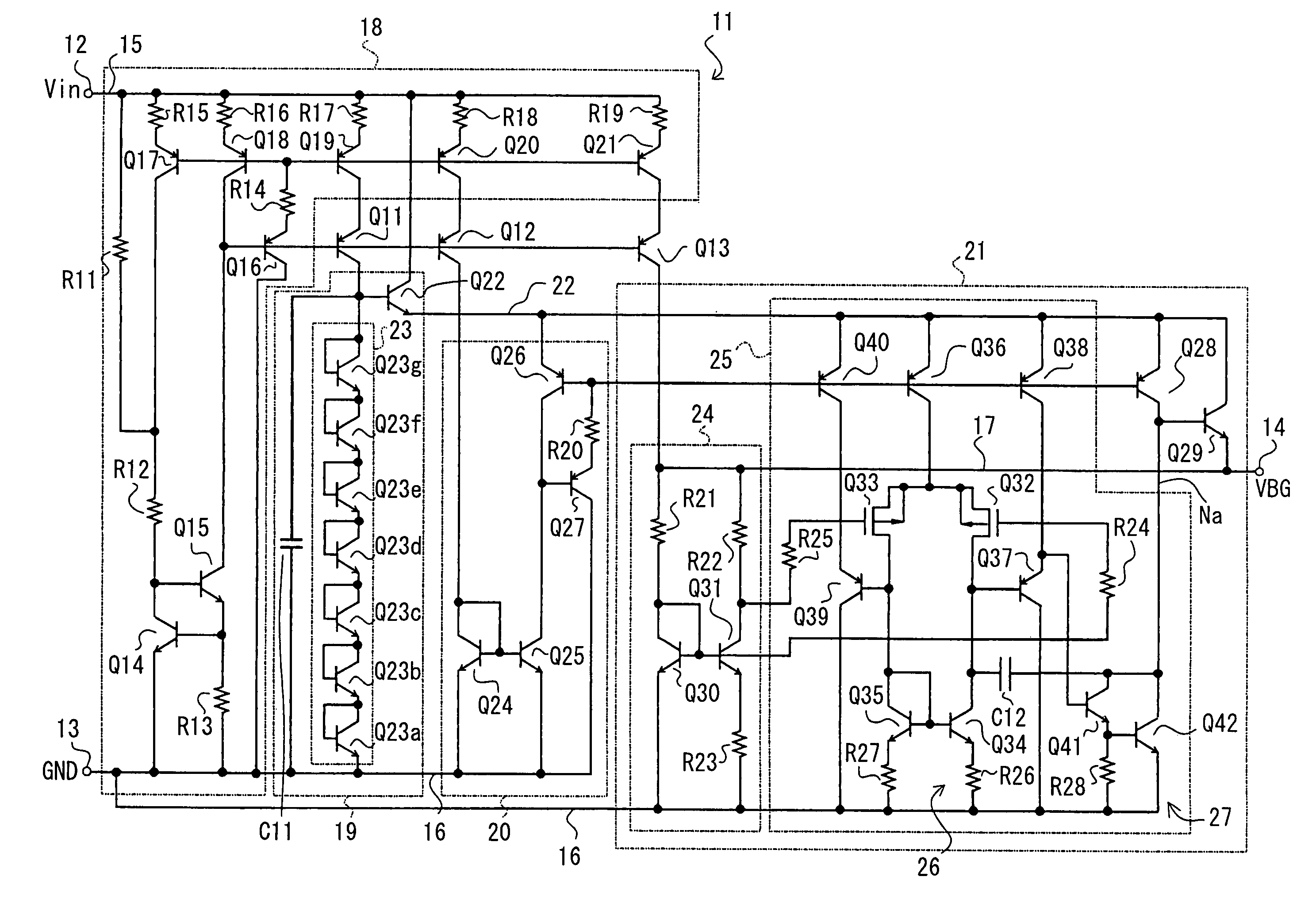
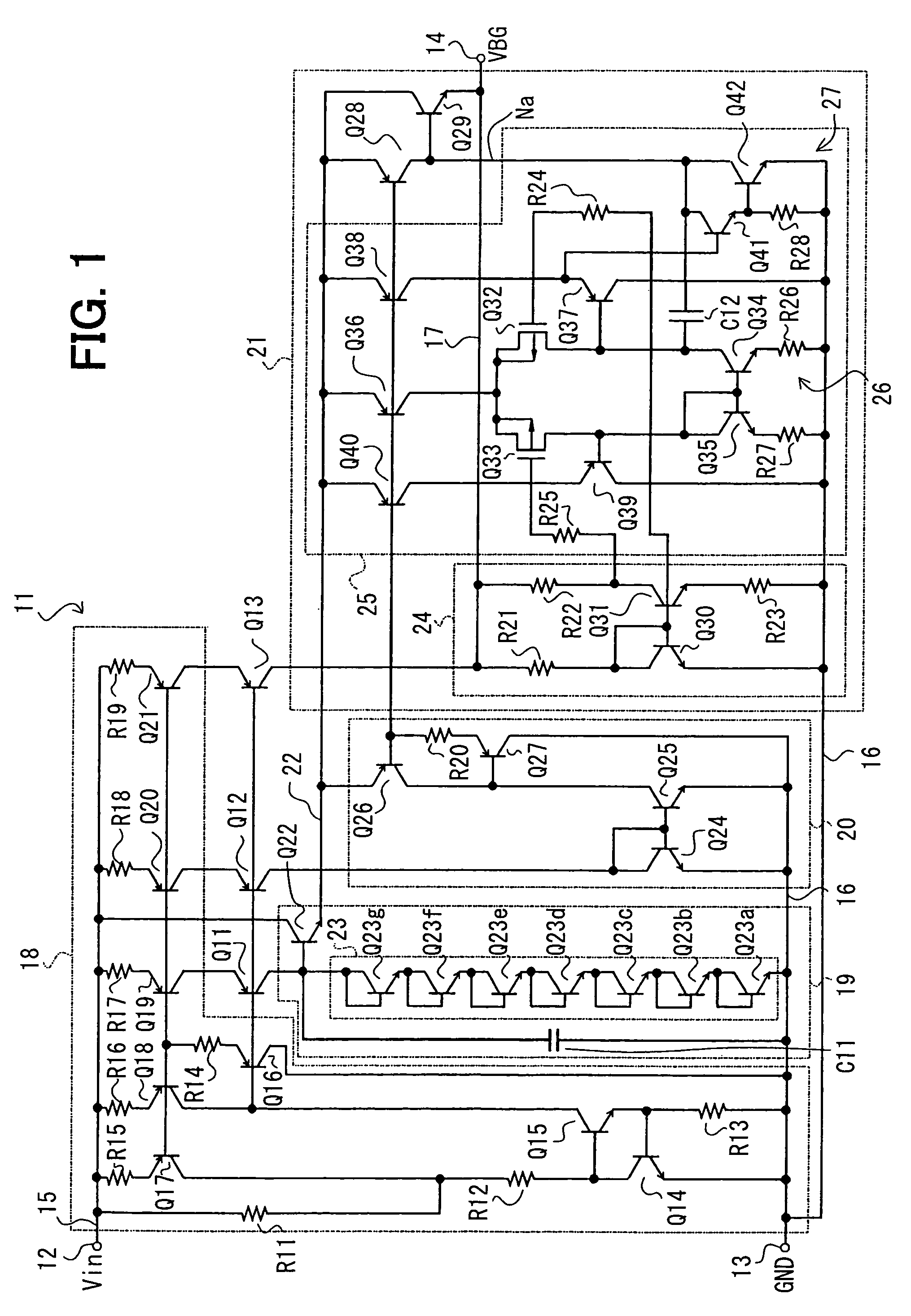
[0024]Referring to FIG. 1, the electrical circuit construction of a band-gap reference voltage generating circuit (hereinafter referred to as “reference voltage generating circuit”) will be discussed. The reference voltage generating circuit 11 contains digital circuits such as CPU, a memory, etc., various types of analog circuits, a power supply circuit, etc., and also contains an IC for control used in an electric control unit (ECU) mounted in a vehicle, for example.

[0025]A power source voltage Vin (a battery voltage VB in this embodiment) is applied from the external to the terminals 12, 13 of the IC, and a band-gap reference voltage VBG (hereinafter referred to merely as “reference voltage VBG ”) of 1.22V is output from the terminals 14, 13 of the IC. The reference voltage VBG is extremely small in temperature variation, and supplied to the external and internal circuits of the IC for control. The terminals 12, 13 are connected to the power supply lines 15, 16 (corresponding to ...


PUM


Abstract

In a constant voltage generating circuit and a reference voltage generating circuit, a band-gap circuit operates by using, not a power source voltage, but a constant voltage generated in a constant voltage circuit as a power supply voltage. The constant voltage circuit is equipped with a constant voltage circuit having transistors connected in series and a capacitor, and a transistor is equipped between a constant current circuit and the constant voltage circuit. Furthermore, transistors are added to prevent an early effect of the transistors in the constant current circuit.

Description

CROSS REFERENCE TO RELATED APPLICATION[0001]This application is based upon, claims the benefit of priority of, and incorporates by reference the contents of, Japanese Patent Application No. 2003-160925 filed on Jun. 5, 2003.FIELD OF THE INVENTION[0002]The present invention relates to a constant voltage generating circuit in which a power source voltage is input between an input power supply line and a ground line and also a constant voltage is output between a constant voltage line and the ground line, and a reference voltage generating circuit in which a power source voltage is input between an input power supply line and a ground line and also a band-gap reference voltage is output between a reference voltage line and the ground line.BACKGROUND OF THE INVENTION[0003]JP-A-5-88767 (Patent Document 1) discloses a band-gap reference circuit designed so that a bias current is supplied from two-stage current-coupled current mirror circuits to a band-gap reference generating circuit. Fur...

Claims


Application Information

Patent Timeline
IPC IPC(8): G05F3/20G05F3/30H03F3/343
CPCG05F3/30
Inventor KOYASU, TAKAHISA
Owner DENSO CORP
Why Eureka
Try Eureka