Power transmission belt and belt drive system with the same

Inactive Publication Date: 2006-05-30
BANDO CHEM IND LTD
View PDF9 Cites 1 Cited by
  • Summary
  • Abstract
  • Description
  • Claims
  • Application Information

AI Technical Summary

Benefits of technology

[0006]An object of the present invention is to provide a power transmission belt that can suppress production of abnormal noises between the belt back face and the flat pulley and does not cause side tracking during belt run, and also to provide a belt drive system with the same.
[0007]To attain the above object, in the present invention, each of two directions of consecutive yarn intersections of the warps and wefts formed to stand out from the belt surface, i.e., each of the directions in which lines of bulges formed of the yarn intersections extend, makes a certain angle with the belt widthwise direction. Thus, the lines of bulges make gradual contact in their lengthwise directions with the flat pulley to prevent the lines of bulges from periodically beating the flat pulley, which prevents the occurrence of abnormal noises between the belt back face and the flat pulley. Furthermore, the reinforced fabric is disposed at the belt back face so that the directions of each warp and weft make equal angles with the belt widthwise direction. Therefore, the action of the belt traveling in the direction of the warps and the action of the belt traveling in the direction of the wefts counteract each other, thereby preventing the occurrence of belt side tracking.
[0015]The flexural property of the belt is susceptible to the directions of warps and wefts constituting the woven fabric. To be more specific, as the directions in which the warps and wefts run in the fabric approach the belt lengthwise direction, the belt stiffness becomes higher. Thus, increased bending loss provides reduced power transmission efficiency and increased heat production, resulting in low flexural fatigue resistance. In order to ensure the proper, low flexural stiffness, it is desirable that each of the angles that the direction of warps and the direction of wefts make with the widthwise direction of the belt is smaller than 40°.
[0019]A belt drive system to which the above power transmission belt is applied may be one in which the power transmission belt is wound around a plurality of pulleys and at least one of the plurality of pulleys is formed of a flat pulley that makes contact with the belt back face. According to such a belt drive system, production of abnormal noises can be suppressed effectively.

Problems solved by technology

When this angle exceeds 20°, there arises an inconvenience that belt side tracking during belt run is increased.

Method used


Image

  • Power transmission belt and belt drive system with the same
  • Power transmission belt and belt drive system with the same
  • Power transmission belt and belt drive system with the same

Examples


embodiment 1

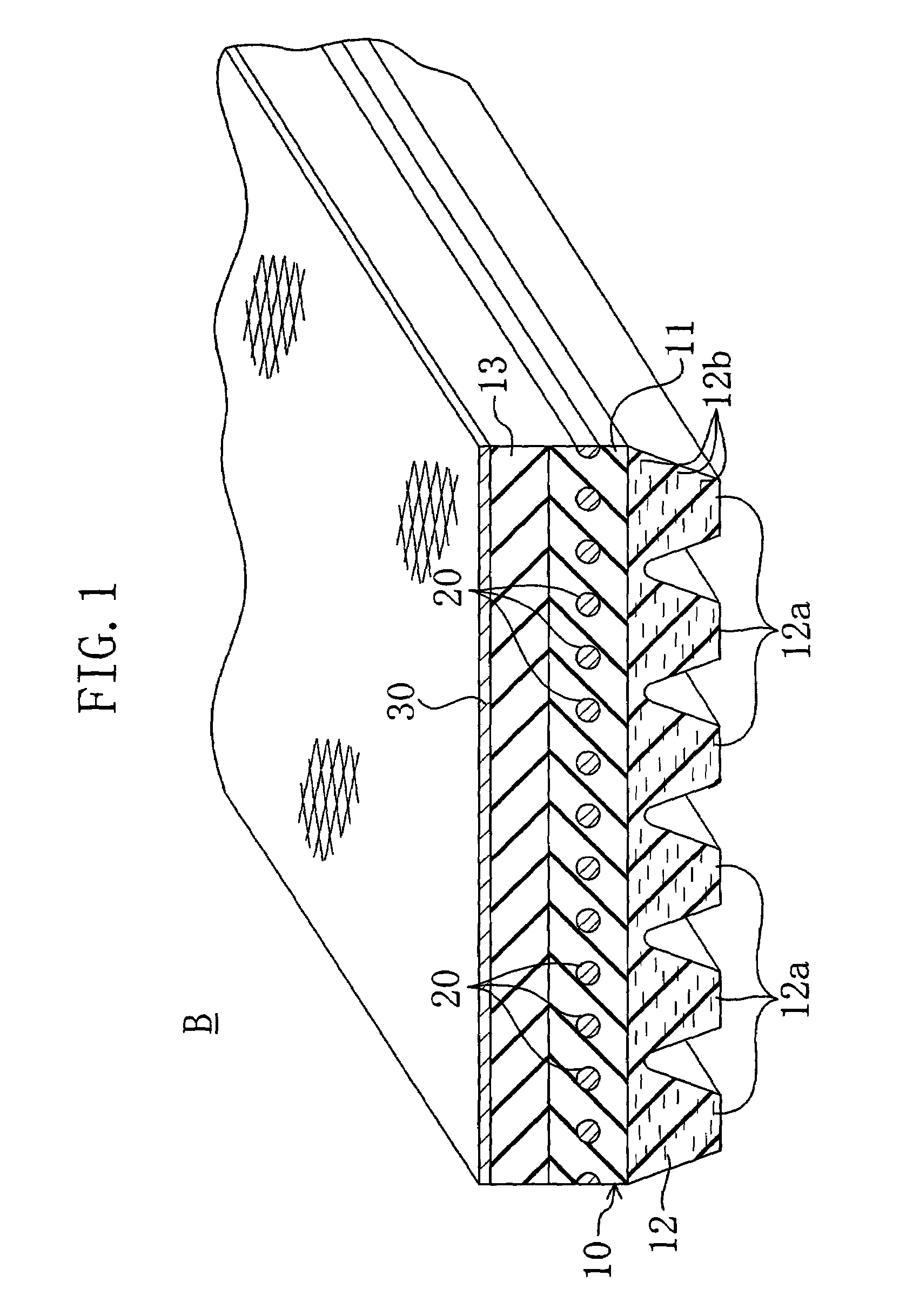
[0033]FIG. 1 shows a V-ribbed belt B according to Embodiment 1.

[0034]This V-ribbed belt B has a V-ribbed belt body 10, a cord 20 embedded in the V-ribbed belt body 10 to form a spiral with certain pitches in the belt widthwise direction, and a reinforced fabric 30 disposed to cover the back face side of the V-ribbed belt body 10.

[0035]The V-ribbed belt body 10 is made of a rubber composition such as chloroprene rubber (CR) or ethylene propylene diene monomer rubber (EPDM). The V-ribbed belt body 10 has a structure in which an adhesion rubber layer 11 containing the cord 20 embedded therein, a rib rubber layer 12 located under the adhesion rubber layer 11, and a tension rubber layer 13 located over the adhesion rubber layer 11 to form a back face part of the belt are stacked into one. The rib rubber layer 12 located at the inner periphery side of the belt forms a part for coming into contact with the pulley to transmit power directly thereon. Therefore, in the rib rubber layer 12, ri...

embodiment 2

[0046]FIG. 5 shows the back face of a V-ribbed belt B according to Embodiment 2. Note that the same reference characters refer to the same parts as in Embodiment 1.

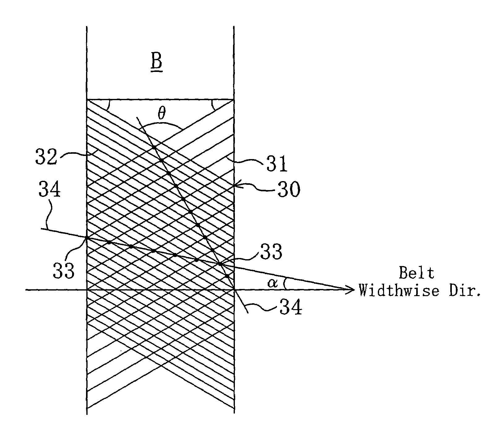
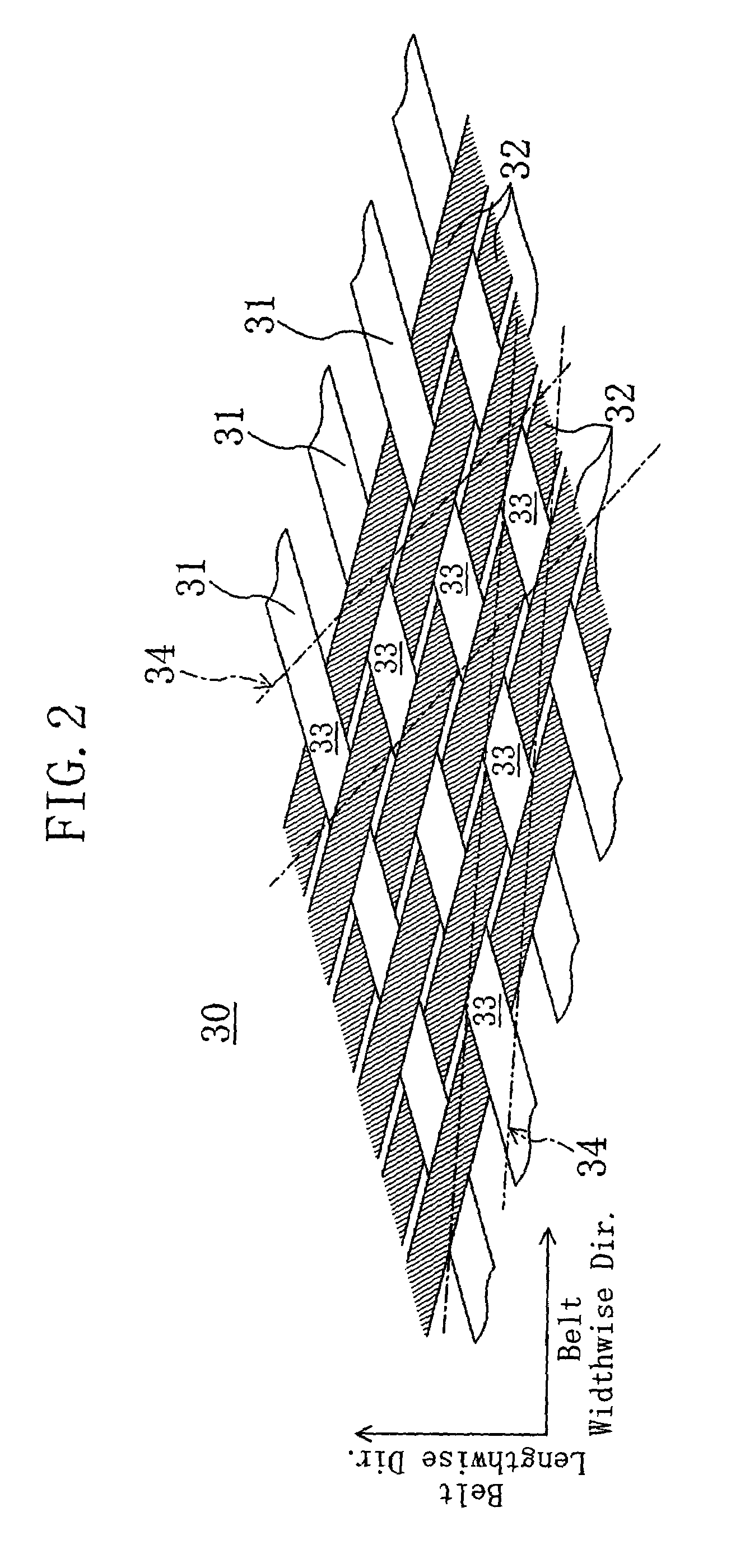
[0047]As shown in FIG. 6, the reinforced fabric 30 of the V-ribbed belt B is formed of a rib weave fabric produced so that the angle formed by the directions of each pair of warp 31 and weft 32 is 100° or more (its supplementary angle is 80° or less). To provide the reinforced fabric 30 with the property of adhesion to the V-ribbed belt body 10, it is subjected, prior to molding, to a series of treatments of soaking into a resorcinol-formaldehyde latex (RFL) liquid and heating, a series of treatments of soaking into a rubber cement and drying, a series of treatments of coating a rubber cement to its surface to be in contact with the V-ribbed belt body 10 and drying, or any possible combinations of them. The rib weave fabric forming the reinforced fabric 30 is woven in weft rib weave that has a pattern in which the wefts 3...

example 1

[0059]As a reinforced fabric, use was made of a plain weave fabric which is formed of mutually crosswise (β=90°) running warps and wefts each made by twisting two 300-dtex polyester / cotton blended yarns and has a warp yarn density of 90 yarns / 5 cm and a weft yarn density of 50 yarns / 5 cm. A V-ribbed belt of EPDM (having seven ribs) was fabricated as Example 1 by covering the belt back face with the reinforced fabric so that each of the directions of the warp and the weft makes an angle of 45° with the belt widthwise direction. In the back face of Example 1 V-ribbed belt, between angles that two directions of consecutive yarn intersections of the warps and wefts formed to stand out from the belt surface, i.e., two directions in which lines of bulges formed of the yarn intersections extend, make with the belt widthwise direction, the smaller angle (α) was 7°, and the pitch of the lines of bulges was 0.86 mm.


PUM

PropertyMeasurementUnit
Angleaaaaaaaaaa
Angleaaaaaaaaaa
Angleaaaaaaaaaa

Abstract

A power transmission belt is formed so that the back face side of a belt body is covered with a reinforced fabric woven with warps and wefts. In the reinforced fabric, the direction of warps and the direction of wefts make equal angles with the belt widthwise direction, and each of two directions of consecutive yarn intersections of the warps and wefts formed to stand out from the belt surface makes a certain angle with the belt widthwise direction.

Description

BACKGROUND OF THE INVENTION(a) Field of the Invention[0001]This invention relates to power transmission belts and belt drive systems with the same.(b) Description of the Prior Art[0002]V-ribbed belts are power transmission belts combining the flexibility of flat belts and the high power transmission capacity of V-belts, and are widely used, for example, as automotive accessory drive belts. In a V-ribbed belt of such kind, in order to allow it to withstand a side pressure and enhance the resistance of the back face part to vertical cracking, the back face side of the belt body is covered with a plainly woven reinforced fabric. In the V-ribbed belt, as shown in FIG. 11, the reinforced fabric 30′ is normally disposed at the belt back face so that the directions of warps 31′ and wefts 32′ form equal angles with the widthwise direction of the belt.[0003]In recent years, as belt drive systems for driving automotive accessories, serpentine drive type ones have been increasingly employed wh...

Claims


Application Information

Patent Timeline
IPC IPC(8): F16G1/04F16H7/02F16G1/00F16G1/08F16G5/00F16G5/06F16G5/20
CPCF16G5/20F16H7/02
Inventor NAKAMOTO, YUJIKAWAHARA, HIDEAKIFUJIWARA, KATSUYOSHISUZUKI, TOMOAKI
Owner BANDO CHEM IND LTD
Why Eureka
Try Eureka