Air barrier device for protecting liquid fluids in opened containers
a technology for protecting liquid fluids and containers, which is applied in the direction of liquid handling, containers preventing decay, instruments, etc., can solve the problems few customers are willing to wait for a bottle of wine, and the quality of wine exposed to oxygen suffers a loss, etc., and achieves the effect of convenient use and convenient dispensing
- Summary
- Abstract
- Description
- Claims
- Application Information
AI Technical Summary
Benefits of technology
Problems solved by technology
Method used
Image
Examples
second embodiment
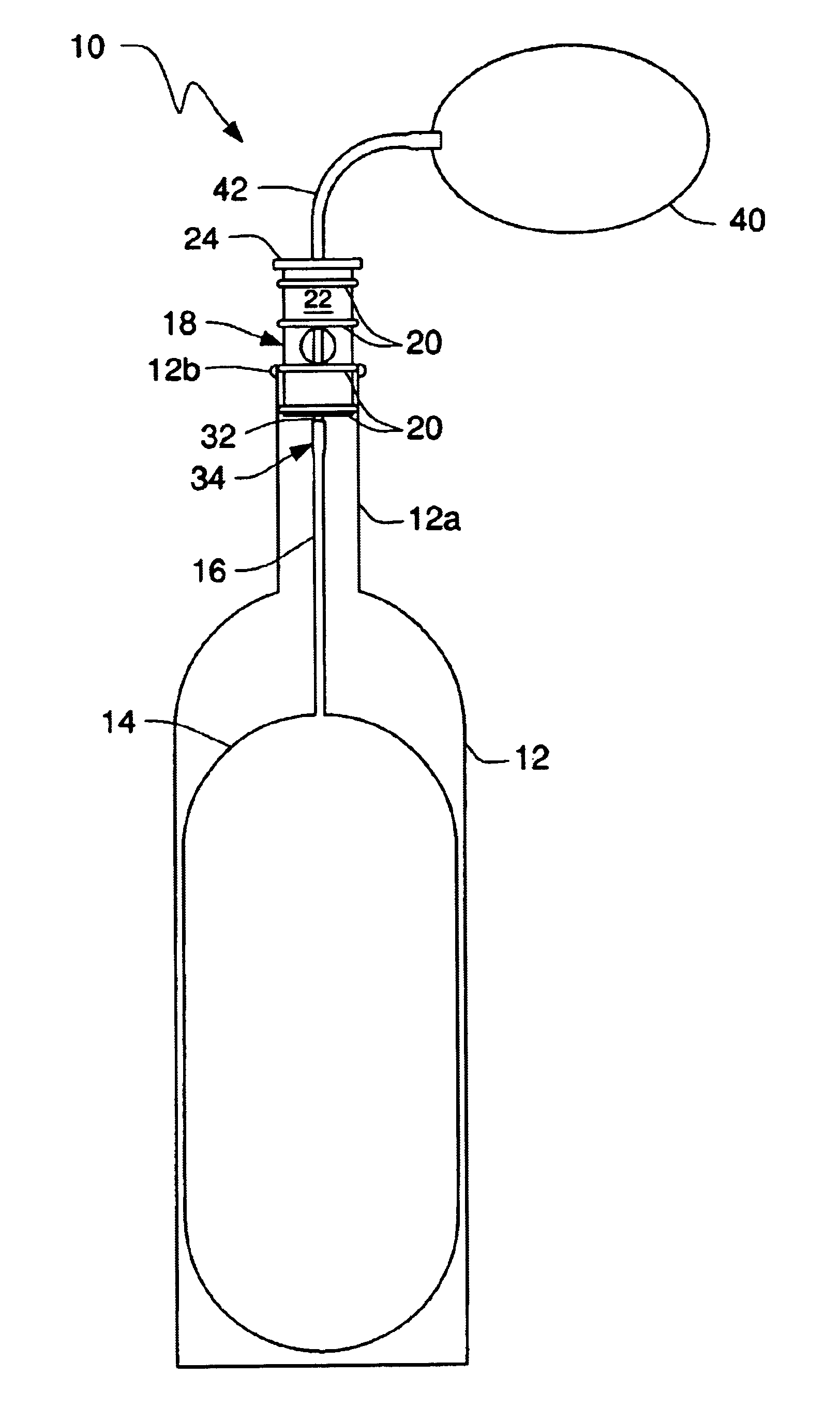
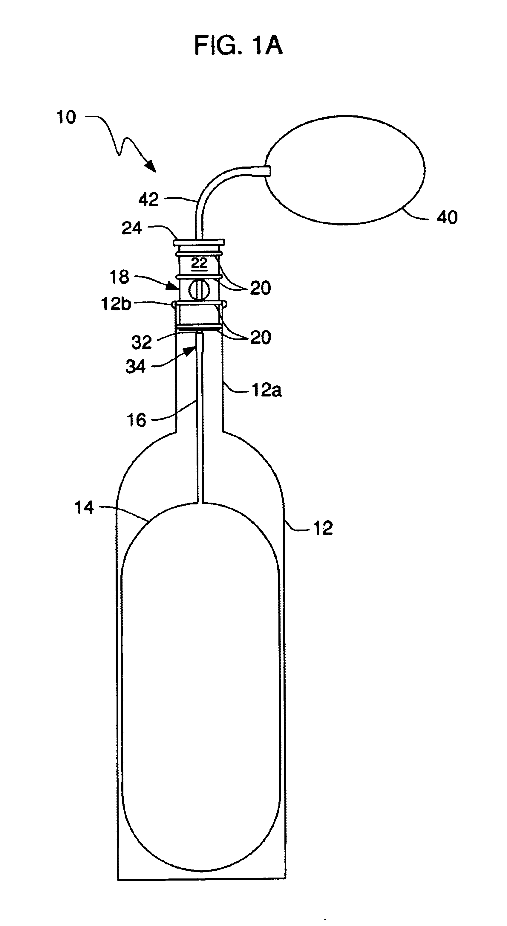
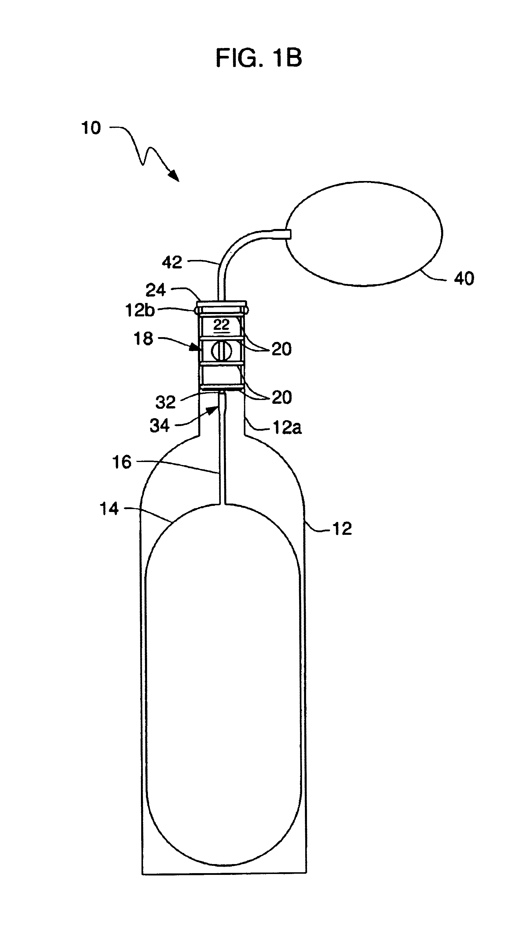
[0091]FIG. 5 depicts a second embodiment where squeeze bulb 40 and flexible neck 42 are eliminated in favor of a more advanced pump structure denoted 44 as a whole. Pump 44 includes a main body 46, a boss 48 that surmounts said main body, plunger 50, and handle 52 secured to the trailing end of plunger 50. An outlet nozzle, not illustrated, positioned at the leading end of main body 46, is in fluid communication with the upper end of mounting tube 32 so that operation of the inflating means causes air to flow through the mounting tube into the bladder.
[0092]Locking device 54 holds handle 52 in its fully “down” position when said locking device engages boss 48 and is turned one half revolution. When so locked, plunger 50 cannot travel upwardly and no wine can be dispensed.
[0093]A pump mechanism within pump body 46, not illustrated to simplify the drawing, pushes air into bladder 14 on the down stroke of handle 52.
[0094]Air enters the wine chamber (the hollow interior of bottle 12) if...
fourth embodiment
[0097]A fourth embodiment is depicted in FIGS. 9 and 10. The radially-disposed part 68a of air duct 68 is formed in enlarged top part 22a of stopper 18a. The longitudinally-disposed part 68b thereof extends from the radially-innermost end of said radially-disposed part 68a to bottom wall 30 of said stopper. Mounting tube 32 has a longitudinally-extending section disposed in longitudinally-disposed part 68b of air duct 68 and a ninety degree (90°) bend is formed in said mounting tube so that a radially-extending part thereof extends into said radially-extending part 68a of said air duct 68.
first embodiment
[0098]An air pump like that of the first embodiment may be employed to pump air into bladder 14 through said air duct 68.
[0099]In the alternative, as in the other embodiments, no mounting tube is employed and the outlet nozzle of the air pump is inserted directly into radially-disposed part 68a of the air duct.
[0100]In this fourth embodiment, base 22 of stopper 18 is hollow, forming wine duct 70, as indicated in FIG. 10. Thus, wine duct 70 of this embodiment extends from the top wall of the stopper to the bottom wall thereof. Cap 72 includes top wall 74 and plug 76. Plug 76 is press fit into the upper end of wine duct 70 of stopper 18 and top wall 74 limits the insertion depth of said plug 74 because its diameter exceeds the inner diameter of said wine duct 70.
[0101]To decant wine from bottle 12, flexible neck 16 of bladder 14 is connected to the lower end of mounting tube 32, (or, as in the other embodiments, the upper end of a mounting tube attached to the bladder is inserted into...
PUM
 Abstract
Description
Claims
Application Information
 - R&D
- Intellectual Property
- Life Sciences
- Materials
- Tech Scout
- Unparalleled Data Quality
- Higher Quality Content
- 60% Fewer Hallucinations
Browse by: Latest US Patents, China's latest patents, Technical Efficacy Thesaurus, Application Domain, Technology Topic, Popular Technical Reports.
© 2025 PatSnap. All rights reserved.Legal|Privacy policy|Modern Slavery Act Transparency Statement|Sitemap|About US| Contact US: help@patsnap.com


