
Hydroform process and hydroform product

a technology of hydroform and process, applied in the field of hydroform, can solve the problems of insufficient countermeasures, difficult to obtain a predetermined rigidity, and increase the difficulty of forming a product,

Inactive Publication Date: 2006-05-30
MITSUBISHI MOTORS CORP
View PDF19 Cites 22 Cited by
  • Summary
  • Abstract
  • Description
  • Claims
  • Application Information

AI Technical Summary

Benefits of technology

[0027]Therefore, even if parts of the assisting member are brought into contact with the die during hydroforming, the original tube member inside the assisting member can be expanded so that its wall thickness will be kept substantially uniform in the circumferential direction. According to the present invention, even if a cross section of a hydroform product is complicated, the original tube member can be expanded so that wall thickness of the original tube member is substantially uniform in the circumferential direction.
[0028]In the invention, it is preferable that the assisting member is a tubular member fitted on the outer peripheral surface of the original tube member. When this assisting member is used, the outer peripheral surface of the original tube member is in tight contact with the inner surface of the assisting member as the original tube member is expanded. Therefore, in accordance with the plastic flow of the material of the assisting member near the predetermined portion, corresponding portions of the original tube member are smoothly extended, which enables smooth expansion of the entire original tube member.
[0030]The present invention utilizes the above-described feature of the hydroform process, thereby providing a hydroform product of a high rigidity in which circumferential non-uniformity of the wall thickness of the original tube member is suppressed.

Problems solved by technology

Thus, in a hydroform product having a complicated cross section, the wall thickness is liable to be circumferentially non-uniform, which makes it difficult to obtain a predetermined rigidity.
Moreover, if a portion of the steel pipe 6 is extremely extended, it becomes extremely thin and hence may be damaged.
However, this countermeasure is not sufficient, and a further improvement is demanded.

Method used


Image

  • Hydroform process and hydroform product
  • Hydroform process and hydroform product
  • Hydroform process and hydroform product

Examples


Embodiment Construction

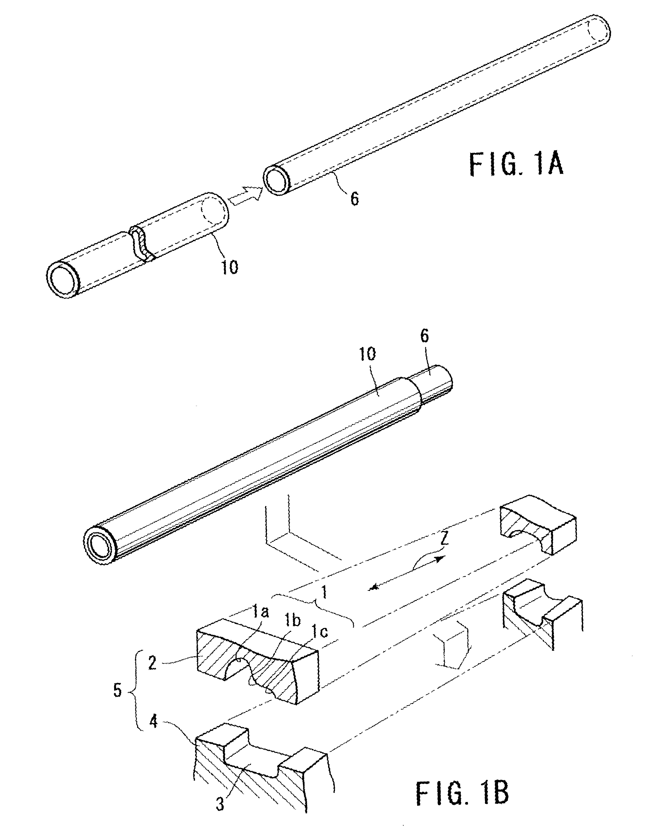
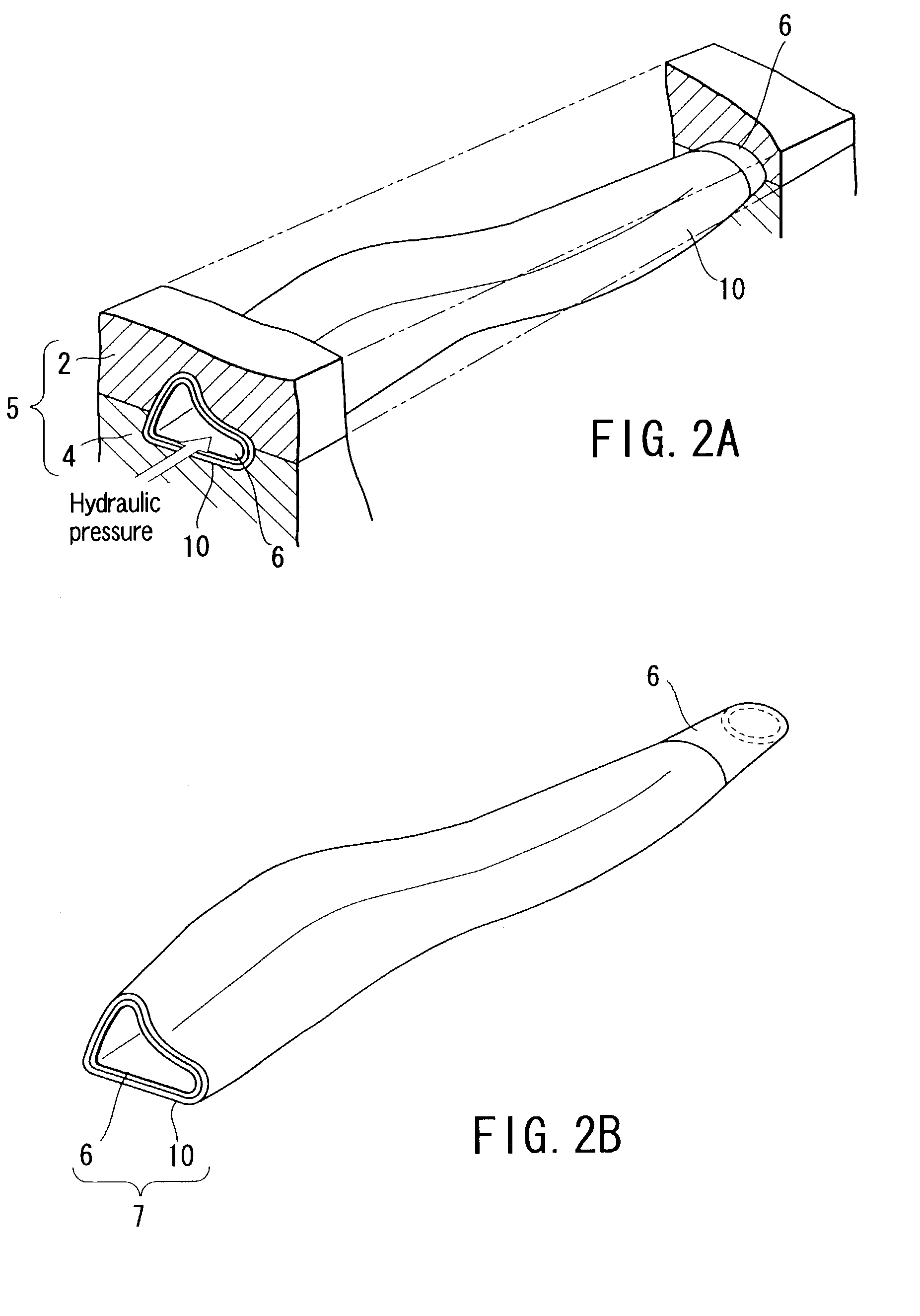
[0048]Referring to FIGS. 1A to 4, an embodiment of the invention will be described.

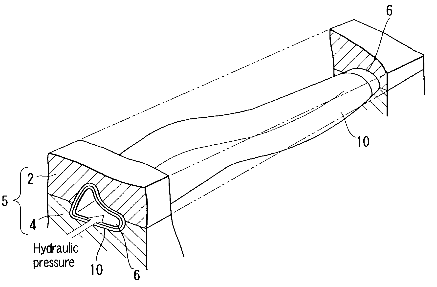
[0049]In the embodiment, a description will be given of the case where a reinforcing member 7 as an example of a hydroform product is obtained by a hydroform process. As shown in FIG. 2B, the reinforcing member 7 has a complicated cross section that has a projection and indent at predetermined circumferential portions.

[0050]The reinforcing member 7 is a composite member formed of a steel pipe 6 corresponding to the original tube member specified in the present invention, and a deformation assisting member 10 corresponding to the assistant member specified in the present invention.

[0051]When hydroforming the reinforcing member 7, the deformation assisting member 10 is attached to the steel pipe 6 beforehand, in order to assist deformation of the steel pipe 6. Hydroforming of the steel pipe 6 is executed using the deformation assisting member 10. In this embodiment, a substantially uniform wall thicknes...


PUM

PropertyMeasurementUnit
Lengthaaaaaaaaaa
Areaaaaaaaaaaa
Deformation enthalpyaaaaaaaaaa

Abstract

When hydroforming a steel pipe, a tubular deformation assisting member made of an incompressible material softer than the steel pipe is fitted on the outer peripheral surface of the steel pipe. The deformation assisting member is attached at least to an area corresponding to a projection provided at the inner surface of the die assembly, the projection being earliest brought into contact with the outer peripheral surface of the steel pipe during hydroforming. When hydroforming the steel pipe, the material of the deformation assisting member plastically flows near corner portions at which the deformation assisting member is brought into contact with the projection.

Description

CROSS-REFERENCE TO RELATED APPLICATIONS[0001]This is a Continuation Application of PCT Application No. PCT / JP02 / 04741, filed May 16, 2002, which was not published under PCT Article 21(2) in English.[0002]This application is based upon and claims the benefit of priority from the prior Japanese Patent Application No. 2001-152775, filed May 22, 2001, the entire contents of which are incorporated herein by reference.BACKGROUND OF THE INVENTION[0003]1. Field of the Invention[0004]The present invention relates to a hydroform process for forming an original tube member, using a die having portions to be brought into contact with the outer peripheral surface of the original tube member, and also relates to a hydroform product obtained by the hydroform process.[0005]2. Description of the Related Art[0006]In the field of reinforcing members for reinforcing each section of vehicles such as automobiles, the employment of reinforcing members formed by hydroforming an original tube member is now ...

Claims


Application Information

Patent Timeline
IPC IPC(8): F16L9/14B21D26/033
CPCB21D26/033B21D53/88B21D47/02B21D26/051
Inventor TAKAHASHI, JUNICHI
Owner MITSUBISHI MOTORS CORP
Learn More