
Optical storage medium

a technology of optical storage medium and optical storage medium, which is applied in the direction of mechanical recording, instruments, transportation and packaging, etc., can solve the problem of inability to record additional medium-related information

Active Publication Date: 2006-05-23
RAKUTEN GRP INC
View PDF9 Cites 28 Cited by
  • Summary
  • Abstract
  • Description
  • Claims
  • Application Information

AI Technical Summary

Benefits of technology

[0010]Moreover, the present invention provides an optical disk comprising: a transparent substrate having a recording layer thereon, information to be recorded on the recording layer being reproducible with irradiation of a laser beam; a reflective layer formed on the recording layer; and a hardcoat layer formed on a surface of the substrate opposite to another surface thereof having the recording layer thereon, the laser beam being incident to the hardcoat layer in reproduction, the hardcoat layer including ultraviolet-hardened resin and at least one type of photochromic dye, the photochromic dye being stable against the laser beam.

Problems solved by technology

In contrast, dual-substrate-type optical storage media such as DVDs do not have a space for such a label layer due to their disk diameter of 120 mm, center-hole diameter of 15 mm and inner storage-zone diameter of 46 mm, like CDs, thus, recording additional medium-related information being impossible.

Method used


Image

  • Optical storage medium
  • Optical storage medium
  • Optical storage medium

Examples


first embodiment

[0032][First Embodiment]

[0033]Illustrated in FIG. 1 is a cross section of a first embodiment of optical storage medium according to the present invention.

[0034]An optical storage medium 10 shown in FIG. 1 is a single-layer DVD-type optical storage medium.

[0035]A transparent base substrate 4 is made of polycarbonate resin having 0.6 mm in thickness and 120 mm in diameter. The base substrate 4 may not be transparent. Formed on the substrate 4 is a recording layer 4a, information recorded thereon being optically reproducible. Formed on the recording layer 4a is a reflective layer 3 made of 70-nm-thick aluminum.

[0036]Provided on the reflective layer 3 is a 40-μm-thick dye-contained bonding layer 2. Bonded on the bonding layer 2 is a transparent substrate 1 having 0.6 mm in thickness and 120 mm in diameter.

[0037]Formed on the base substrate 4 but opposite to the reflective layer 3 is a 20-μm-thick label layer 5. In detail, the label layer 5 is formed by screen printing with dye (pigment)...

second embodiment

[0095][Second Embodiment]

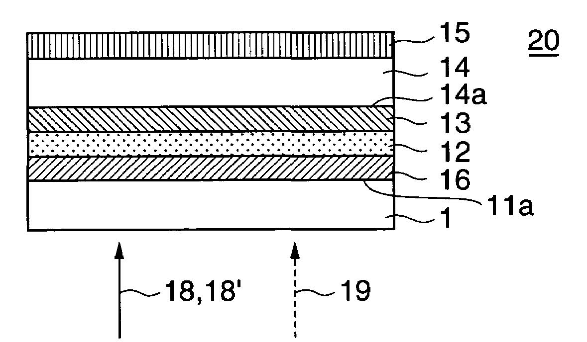
[0096]Illustrated in FIG. 5 is a cross section of a second embodiment of optical storage medium according to the present invention.

[0097]An optical storage medium 20 shown in FIG. 5 is a dual-layer DVD-type optical storage medium.

[0098]A transparent substrate 11 and a transparent base substrate 14 are made of polycarbonate resin, both having 0.6 mm in thickness and 120 mm in diameter. The base substrate 14 may not be transparent. Formed on the substrates 11 and 14 are recording layers 11a and 14a, respectively, information recorded thereon being optically reproducible.

[0099]Formed on the recording layer 11a is a semi-transparent reflective layer 16 made of gold or silicon having thickness in the range from 5 nm to 10 nm. Formed on the recording layer 14a is a reflective layer 13 made of 70-nm-thick aluminum.

[0100]The transparent substrate 11 and the base substrate 14 are bonded each other via a 40-μm-thick dye-contained bonding layer 12 so that the semi-tran...

third embodiment

[0106][Third Embodiment]

[0107]Illustrated in FIG. 6 is a cross section of a third embodiment of optical storage medium according to the present invention.

[0108]An optical storage medium 30 shown in FIG. 6 is a single-layer CD-type optical storage medium.

[0109]A transparent substrate 21 is made of polycarbonate resin, having 1.2 mm in thickness and 120 mm in diameter. Formed on the substrate 21 is a recording layer 21a, information recorded thereon being optically reproducible.

[0110]Formed on the recording layer 21a is a reflective layer 23 made of 70-nm-thick aluminum. Provided on the reflective layer 23 is a 10-μm-thick protective layer 26 made of epoxyacrylate resin which is ultraviolet-hardened resin.

[0111]Formed on the protective layer 26 is a 20-μm-thick label layer 25. In detail, the label layer 25 is formed by screen printing with pigment (dye)-contained ultraviolet-hardened resin. Recorded on the label layer 25 is information related to the contents recorded on the optical s...


PUM


Abstract

An optical disk has a first substrate having a recording layer thereon, information to be recorded on the recording layer being reproducible with irradiation of a laser beam, a reflective layer formed on the recording layer, and a second transparent substrate, the laser beam being incident to the second substrate in reproduction. The first and the second substrates are bonded to each other by a bonding layer via the reflective layer. The bonding layer includes ultraviolet-hardened resin and at least one type of photochromic dye that is stable against the laser beam. In another type, the first substrate maybe transparent. Instead of the second substrate, this type has a hardcoat layer formed on a surface of the first substrate opposite to another surface thereof having the recording layer thereon, the laser beam being incident to the hardcoat layer in reproduction. The hardcoat layer includes ultraviolet-hardened resin and at least one type of photochromic dye that is stable against the laser beam.

Description

BACKGROUND OF THE INVENTION[0001]The present invention relates to an optical storage medium. Particularly, this invention relates to an optical storage medium having an information-visible zone indicating additional medium-related information.[0002]Compact discs (CD) and digital versatile discs (DVD) are popular optical storage media.[0003]Single-substrate-type optical storage media such as CDs have an information-visible zone on a label layer indicating additional medium-related information on the medium surface opposite to the signal-reproducing surface, by silk screen printing or offset printing.[0004]In contrast, dual-substrate-type optical storage media such as DVDs do not have a space for such a label layer due to their disk diameter of 120 mm, center-hole diameter of 15 mm and inner storage-zone diameter of 46 mm, like CDs, thus, recording additional medium-related information being impossible.[0005]In order to overcome such a problem, Japanese Unexamined-Patent Publication N...

Claims


Application Information

Patent Timeline
IPC IPC(8): G11B3/70G11B7/0037G11B7/24024G11B7/24027G11B7/24094G11B7/24097G11B7/252G11B7/256
CPCG11B7/0037G11B7/24018G11B7/24094G11B7/252Y10T428/21G11B7/24038
Inventor TSUJITA, KOUJIOKUMURA, MIKIO
Owner RAKUTEN GRP INC
Learn More