Method for driving light deflector, light deflector, light deflection array, image forming device, and image projection display apparatus
a technology of image forming device and driving light, which is applied in the direction of optics, instruments, optical elements, etc., can solve the problems of high cost of manufacturing projection type image forming device, high cost of ensuring beam stability, and high response speed
- Summary
- Abstract
- Description
- Claims
- Application Information
AI Technical Summary
Benefits of technology
Problems solved by technology
Method used
Image
Examples
first embodiment
(First Embodiment)
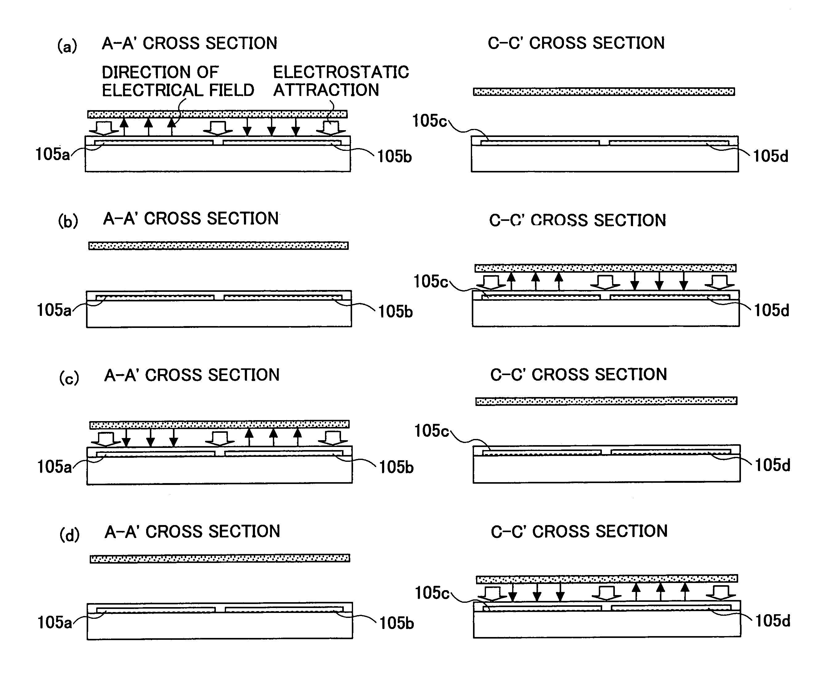
[0133]FIG. 5 is a cross-sectional view showing a method for driving a light deflector of the first embodiment of the present invention. The first embodiment is an example wherein the light deflector of the present invention shown in FIG. 4 is stably light-deflection-operated. FIG. 5-(a) through FIG. 5-(d) are cross-sectional views of the light deflector taken along the planes A–A′ and C–C′ at the time of light deflection operations. FIG. 5-(a) corresponds to step 1. FIG. 5-(b) corresponds to step 2. FIG. 5-(c) corresponds to step 3. FIG. 5-(d) corresponds to step 4.
[0134]Directions of electrical fields generated by electric potentials applied to the electrodes 105a–105d are shown by black arrows and electrostatic attractions shown by white arrows in FIG. 5-(a), FIG. 5-(b), FIG. 5-(c), and FIG. 5-(d).
[0135]FIG. 6 is a timing chart of electric potentials applied to electrodes in the method for driving the light deflector of the first embodiment. In FIG. 6, the electr...
second embodiment
(Second Embodiment)
[0142]FIG. 7 is a timing chart of electric potentials applied to electrodes in the method for driving the light deflector of the second embodiment. In FIG. 7, an electric potential “x” is an electric potential having a half value of a positive electric potential. Referring to FIG. 7, the method for driving the light deflector of the second embodiment of the present invention and tilt displacement operations (light deflection operations) of the plate shape member 104 corresponding to the method are discussed. In the method for driving the light deflector of the second embodiment of the present invention, an electric potential of either of different electric potentials of the method for driving the light deflector of the first embodiment is a positive electric potential, another electric potential of different electric potential of the method for driving the light deflector of the first embodiment is ground potential, and an intermediate electric potential is a half...
third embodiment
(Third Embodiment)
[0149]FIG. 8 is a timing chart of electric potentials applied to electrodes in the method for driving the light deflector of the third embodiment. In FIG. 8, although the polarity of a positive electric potential is different from the polarity of a negative electric potential, both of them have substantially the same value. Referring to FIG. 8, the method for driving the light deflector of the third embodiment of the present invention and tilt displacement operations (light deflection operations) of the plate shape member 104 corresponding to the method are discussed. In the method for driving the light deflector of the third embodiment of the present invention, an electric potential of either of different electric potentials of the method for driving the light deflector of the first embodiment is a positive electric potential, another electric potential of the different electric potentials of the method for driving the light deflector of the first embodiment is a ...
PUM
 Abstract
Description
Claims
Application Information
 - R&D
- Intellectual Property
- Life Sciences
- Materials
- Tech Scout
- Unparalleled Data Quality
- Higher Quality Content
- 60% Fewer Hallucinations
Browse by: Latest US Patents, China's latest patents, Technical Efficacy Thesaurus, Application Domain, Technology Topic, Popular Technical Reports.
© 2025 PatSnap. All rights reserved.Legal|Privacy policy|Modern Slavery Act Transparency Statement|Sitemap|About US| Contact US: help@patsnap.com


